 Русский
 Français
 Chinese
How we understand what is fixed on the DRM graph?
Power grid companies are obliged to use OLTCs more often for the intended purpose (on-load tap changing) due to new strict requirements for the electricity quality (particularly, for the level of network electrical voltage). That causes the demand for an appropriate diagnostic equipment and, as a result, the emergence of various instruments and methods of OLTC monitoring.
There are two methods to analyze an OLTC device: demountable - with opening the tank (partial or full oil drain) and non-demountable called DRM (Dynamic Resistance Measurement).
The principle of DRM is to measure instantaneous current values. The current flows first through the transformer winding, and then through the contacts of an OLTC while switching from tap to tap. A DRM graph (oscillogram) is constructed, based on measurements results. It shows changes in current force at the moments of switching contacts. This graph allows you to determine the time of switching from tap to tap, as well as the general technical condition of the object being checked.
Undoubtedly, there is an important demountable diagnostic, but a number of problems and malfunctions can be identified with non-demountable DRM method, that helps to save a huge amount of time and money.
The mode of non-demountable diagnostic by the DRM method is realized in a specialized instrument PKR-2M, as well as in milli-ohmmeters MIKO-8M(A) and MIKO-9A.
In MIKO-8M(A) and MIKO-9A milli-ohmmeters, the DRM mode is not the main one because the instruments are primarily designed to measure resistance. However, the presence of this mode mutually complements the main purpose and gives more complete information about the state of a power transformer.
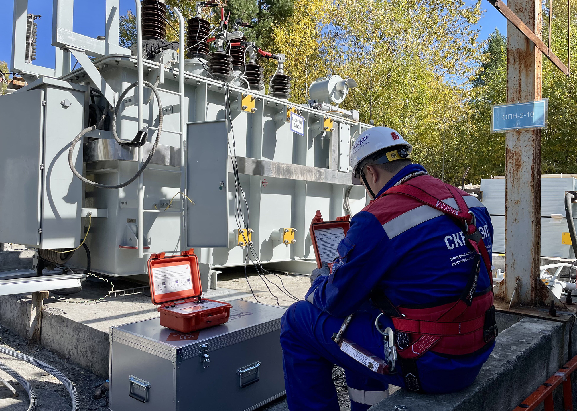

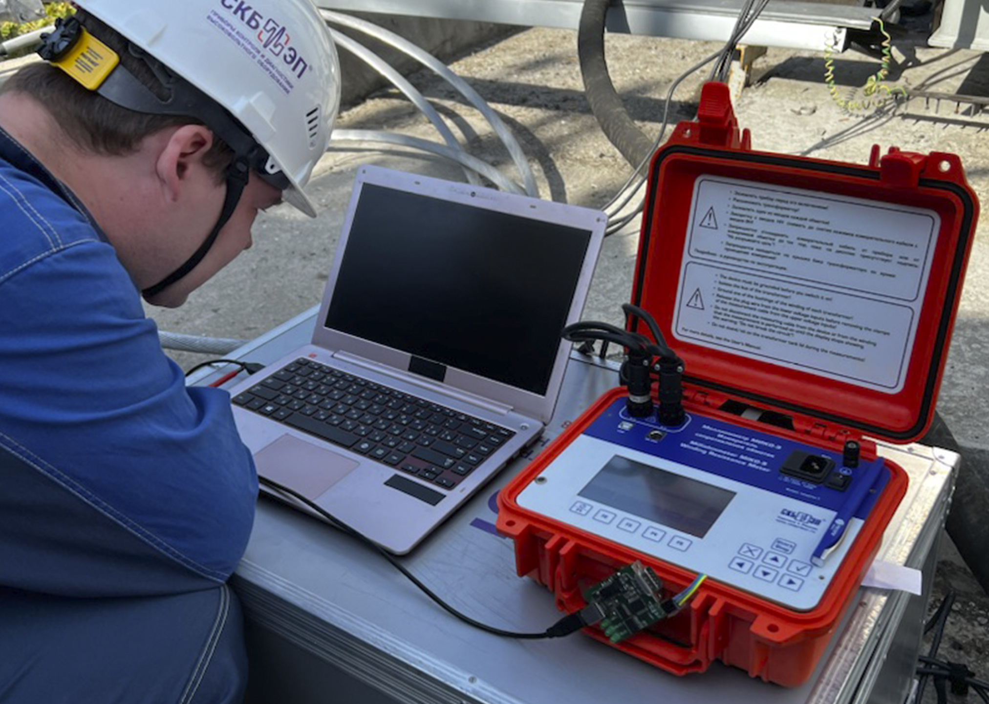
Within current tests SKB EP`s specialists have carried out work on a three-phase power transformer - SFZ11-10C00/35 with a resistive OLTC device using a modern multifunctional milli-ohmmeter MIKO-9A.
According to the tests results, it is necessary to decrypt an oscillogram and figure out what is hidden on each segment. In this instance a typical oscillogram of a serviceable resistive OLTC device - CVIII – 350Y/40,5 -10193W is shown.

In order to learn how to identify malfunctions, we need to monitor the dynamics and collect a database. We recommend starting such work from the moment when a new equipment is put into operation or after it is checked out with a complete demounting. The ability to analyze DRM graphs makes it possible not only to sort out OLTC devices according to the serviceable / unserviceable but also to indicate the nature of the defect. That gives you an opportunity to exclude unnecessary disassembly of serviceable OLTCs.
The DRM method in OLTCs` monitoring is being implemented more frequently in power grid companies. This is not surprising because repairs works on transformers without proper diagnostic can become not only a waste of money and time, but even a harmful procedure.
If you have a desire to learn how to professionally understand the diagnostic of OLTC devices, you can contact us! SKB EP conducts educational licensed activities for energy specialists. 4 programs have been developed and approved for the training of personnel engaged in the maintenance of power transformers and OLTCs. Interested? We are waiting for your questions by mail skb@skbep.com or by phone +7 (812) 500-25-48.