 Русский
 Français
 Chinese
New development: MIKO-9 four-channel milliohmmeter and its features
New approaches to programming, the development of the energy industry, and the growing needs of energy specialists provide the basis for creating new types of measuring instruments that will meet the necessary requirements and requests. Thus, among the microhmeters and milliohmeters of Russian production, a stable niche is occupied by well-known and proven devices of the MIKO group produced by SKB EP, which have no analogues even in the foreign market with respect to certain parameters.
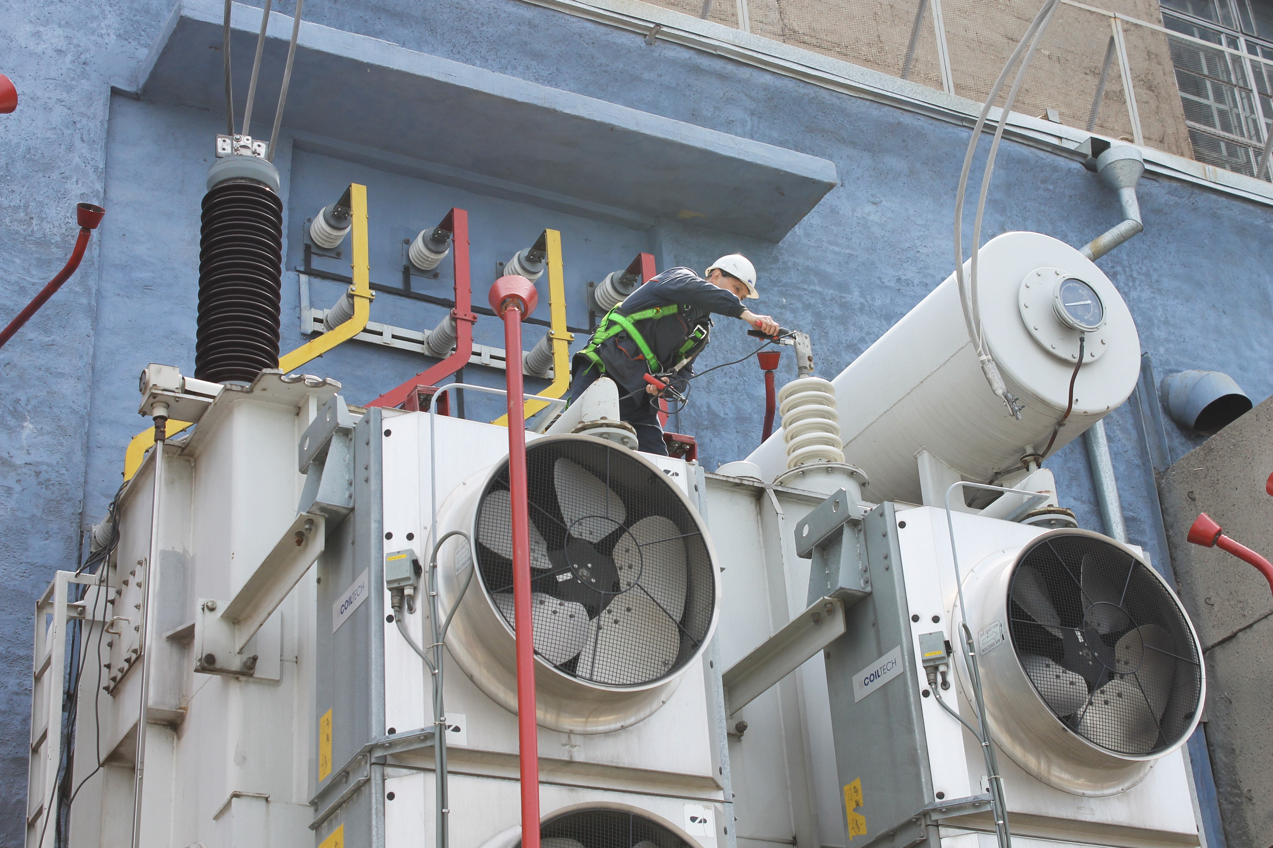
By the end of this year, a new device will be release to the market — the MIKO-9A four-channel milliohmmeter. The instrument allows you to measure the resistance in inductive and non-inductive circuits in the range of 10 μΩ ÷ 30 μΩ at a current of up to 10A (Fig. 1.), providing high accuracy corresponding to class 0.1. This accuracy is maintained not only in laboratory conditions, but also in substations under conditions of industrial interference. This is achieved due to the fact that the maximum possible measuring current limited only by the useful power of the device is calculated and set for any winding resistance. Therefore, the ratio of the useful signal on the winding to the interference amplitude remains high for any resistance (patent for invention "Method for measuring the DC resistance of windings of electrical equipment").
The main distinctive feature of MIKO-9A is the presence of four measuring channels for electrical resistance, and they operate according to two algorithms: "automatic three-phase" mode and "two windings" mode:
The "automatic three-phase" mode consists of sequential automatic measurement in three phases with automatic stop and display of the result. When working in this mode, the user can enjoy significant organizational and technical convenience:
- when measuring electrical resistance of HV and LV three-phase windings, only 3 (three) descents / ascents to the cover of the power transformer, or the cradle of the lift, is required, in contrast to 7 (seven) previously;
- if the OLTC drive fails, its manual turning is very labor-intensive. The instrument also allows you to reduce the number of turning operations 3 (three) times by measuring the resistance of 3 (three) phases of the winding on each branch without reconnecting the cables;
- significant reduction of measurement time due to automatic selection of the algorithm programmed in the instrument with the optimal direction of the measuring current.
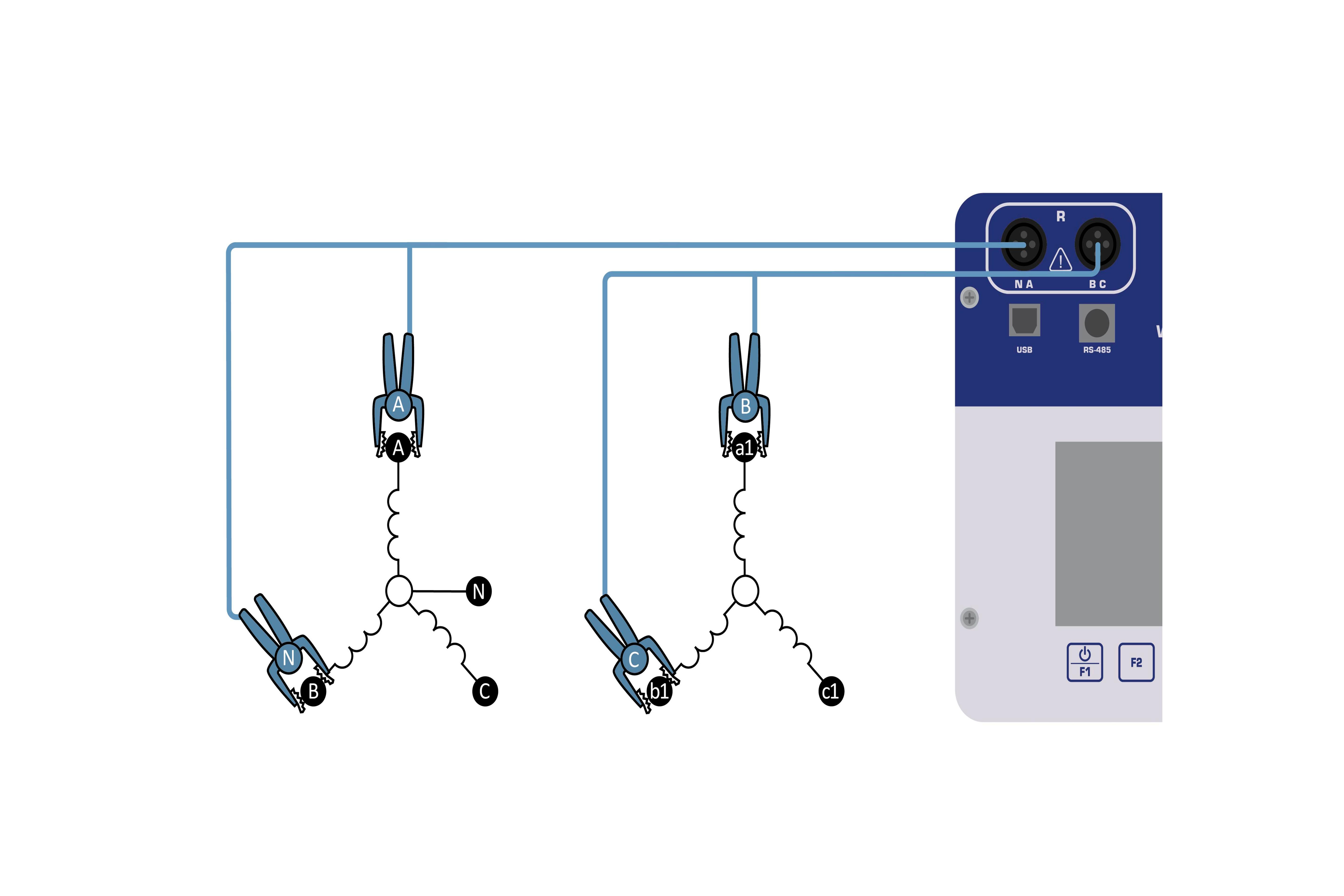
The "two windings" mode is more specific and professional. Here, the measuring current is passed through two series-connected windings with simultaneous measurement of the voltage drop on each of them and subsequent calculation of their resistance. This mode can be used for:
- simultaneous measurement of the electrical resistance of phase/line HV and LV windings (Fig. 2.);
- measurement of resistance of phase Y-connected windings with insulated neutral;
- measurement (with subsequent calculation) of the ratio between the Δ-connected winding.
In the case of high-power transformers, it is recommended to connect the windings to be measured using an external short-circuit cable SKB041.23.00.000, which will increase the measuring current.
In addition to the features associated with four channels for measuring electrical resistance, MIKO-9A has additional functions that transforms the device into a measuring system:
- Database of typical measurement objects (power transformer, current transformer, voltage transformer, resistive object, generator, etc.) allows you to select an object, and the device automatically takes into account its specifics in the diagnosis, thus avoiding additional configuration by the user. In addition, this function makes it easier to organize the results obtained and save them in the company's archives.
- DRM test [3] to check the technical condition of the contactor of OLTC without opening it by connecting it to the transformer inputs. Based on the measurement results, a graph of the current change when switching contacts is plotted, and the switching time and the general technical condition of the device being checked are determined on its basis.
- Cooling test. The test procedure and rules for processing the results meet the requirements of clause 2 of GOST 3484.2-88 Power Transformers. Heating tests [2].
- Demagnetization of the transformer's magnetic system is implemented in accordance with GOST 3484.1-88 [1]. The user can work both in fully automatic mode and in manual mode with a change in the current measurement step up to 1% (thus, the total demagnetization time increases accordingly).
- Complete automation of the measurement process and archive of results in the instrument. Archive of measurements in the instrument is designed to view, copy, or delete the measurement results stored in the nonvolatile memory, and to provide data such as automatic calculation of relative deviations of the electrical resistance of the windings of the three phases between each other; automatic conversion of linear resistance of of Y- or Δ-connected windings, into the electrical resistance of the phase windings; automatic conversion of the electrical resistance of the winding measured at the current temperature, into the electrical resistance at a rated temperature (taking into account the winding material), etc.;
- improve the performance of the power transformer inspection,
- due to multi-channel principle, improve the accuracy of measuring the electrical resistance of the windings of three-phase transformers,
- get additional information about the technical condition of the contactor of the OLTC device.
In addition, the ability to enter the details of the equipment being checked and transfer the measurement results into the automated process control system via both USB and Bluetooth makes it possible for MIKO-9A to meet the requirements of the Digital Energy program.
At the moment, the device is undergoing trial operation for adding it to the State Register of Measuring Equipment. The planned launch date is Q4 2018, but purchase requests are already being accepted.
If you have any questions, please contact our managers by phone +7 (812) 500-25-48 or e-mail skb@skbep.com.
References:
- GOST 3484.1-88. Power transformers. Test methods.
- GOST 3484.2-88. Power transformers. Heating tests.
- Prof. dr. J.J. Smit. On-load Tap Changer Diagnosis on HighVoltage Power Transformers using Dynamic Resistance Measurements.