 Русский
 Français
 Chinese
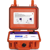
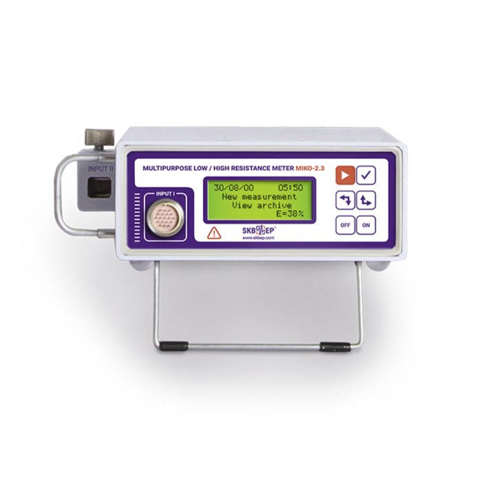
Comparison of SKB EP milli-ohmmeters
Measurement of active resistance of windings is an important stage of maintenance, as well as part of the acceptance test program at the factory. Transformers, electric motors, electromagnets, etc. are subject to vibration, overload and the influence of large temperature drops, which in time leads to the disruption of the connections and requires constant testing with special instruments - milli-ohmmeters.
| MIKO-9А | MIKO-8M(A) | MIKO-7М(А) | MIKO-2.3 | |
 |
 |
 |
 |
|
| Application area | ||||
| Windings of power transformers |
|
|
|
windings of small size transformers |
| Non-demountable estimation of transformers' OLTCs |
|
|
|
|
|
Windings of current and voltage measuring transformers |
with winding resistance up to 30 kΩ |
with winding resistance up to 10 kΩ |
with winding resistance up to 2 kΩ |
with winding resistance up to 1 kΩ |
|
Windings of electromagnets, electric motors and compensators |
|
|
|
|
| Windings of high frequency filters |
|
|
|
|
| Compensatory, current limiting and other resistors of high-voltage circuit breakers |
|
|
|
|
| Contacts and connections of power and signal circuits |
|
|
|
|
| Cables |
|
|
|
|
|
Temperature measurement of water, air, oil (non-aggressive environments) |
|
|
|
|
| General characteristics | ||||
| Measurement range | 1 μΩ ÷ 30 kΩ | 1 μΩ ÷ 10 kΩ | 1 μΩ ÷ 2 kΩ |
100 μΩ ÷ 1 kΩ in milli-ohmmeter mode 0,1 μΩ ÷ 0,1 Ω in micro-ohmmeter mode |
| Test current range |
0,0005 ÷ 10А |
0,001 ÷ 10А |
0,01 ÷ 10А |
0,5 ÷ 5А in milli-ohmmeter mode 10 ÷ 1000А in micro-ohmmeter mode |
| Accuracy | ±(0,1%+0,5 μΩ) |
±(0,1%+0,5 μΩ) |
±(0,1%+0,5 μΩ) |
±0,2% |
| Resolution capability | 0,1 μΩ |
0,1 μΩ |
0,1 μΩ |
0,1 μΩ |
The instrument has protection against:
|
|
|
|
|
| Built-in memory | up to 1,000 measurements | up to 1,000 measurements | up to 200 measurements | up to 100 measurements |
| Display | color graphic TFT touch, 800 x 480 pixels |
color graphic TFT touch, 800 x 480 pixels |
monochrome graphic display, 128 x 64 pix | monochrome, alphanumeric, 6 х 2,5 сm |
| PC connection | By cloud server on PC and through mobile app |
By cloud server on PC and through mobile app |
By cloud server on PC and through mobile app |
RS-232 and USB (when using adapter) |
| Instrument control from mobile app (smartphone) |
Bluetooth |
Bluetooth |
Bluetooth |
|
|
Power supply by built-in battery |
Li-ion battery |
Li-ion battery MIKO-8MA modification |
Li-ion battery MIKO-7MA modification |
Condenser battery is in development. Power supply by an external li-ion battery |
| Mains power supply |
|
|
|
|
| Operating temperature range, ºC | -20 ÷ +55 °С | -20 ÷ +55 °С | -20 ÷ +55 °С | -20 ÷ +40 °С |
| Dimensions, mm | 270х250х130 | 270х250х130 | 270х250х130 | 150х190х75 |
| Instrument weight with battery, kg | 4,0 |
4,0 MIKO-8MA modification |
4,0 MIKO-7MA modification |
- |
| Instrument weight without battery, kg | - | 2,7 | 2,7 | 2,7 |
| Functions | ||||
| High precision measurement modes for different objects, taking into account their specific features |
10 objects |
10 objects |
5 objects |
|
| Automatic or manual measuring current setting |
|
|
|
|
| High precision measurement modes in non-inductive circuits |
|
|
|
|
| Connection directly to the three phases of the transformer and measurement with automatic switching |
|
|
|
|
| Simultaneous resistance measurements across 2 windings, in particular for high-power transformers with secondary windings delta connected when the use of traditional methods does not give a stable result |
|
|
|
|
|
Automatic load inductance meter. The instrument automatically detects the moment of setting the resistance and stops the measurement |
|
|
|
|
|
Automatic inductance discharge after measurement |
|
|
|
|
|
Electric resistance measurement mode of power transformer windings with OLTC device. When switching OLTC devices, the instrument can stay connected |
|
|
|
|
| Winding electrical resistance measurement mode during the cooling test. The test procedure is in accordance with paragraph 2. GOST 3484.2-88 "Power tramsformers. Heating Tests" |
|
|
|
|
| AUTO demagnetization mode of the magnetic transformers system |
|
|
|
|
|
Non-demountable estimation of the OLTCs (DRM test) with generating oscillograms |
|
|
|
|
| Automatic recalculations | ||||
| Automatic calculation of the relative deviations of the electrical resistance at the three-phase windings between each other |
|
|
|
|
| Automatic recalculation of linear electrical resistance of windings delta or star connected into electrical resistance of phase windings |
|
|
|
|
| Automatic recalculation of the electrical resistance of the winding measured at the current temperature into electrical resistance at the passport temperature |
taking into account the winding material |
taking into account the winding material |
|
taking into account the winding material |
| Automatic calculation of deviations of the measured and passport temperature electrical resistance of the windings compared to the passport resistance values |
|
|
|
|
| Automatic calculation of the winding temperature according to its measured and passport value of electrical resistance and passport temperature |
in the cooling test (heat run test) mode |
|
|
|