 Русский
 Français
 Chinese
A Method for Determining the HV Windings Faults Locations in Power Transformers
Measurement of AC electric resistance of power transformer windings is a mandatory test performed during HV power transformer maintenance. The main criterion of determining the winding state (integral/failed) is based on calculation of the relative difference between electric resistances of windings of the same voltage class of different phases. This difference shall not exceed 2%. If this value is exceeded the problem of finding the cause of excess arises. Possible causes may be:
- Problems with contact connections;
- Break of one or several wires in the multi-wire winding cable;
- Winding wire short-circuiting;
- Problems with OLTC contacts.
One of the methods of finding the fault in the electric circuit is its division into separate sections followed by measurement of electric resistance of each section.
In the high-voltage power transformers equipped with the OLTC devices of RS‑3/RS-4/RS-9 type installed in the center of HV winding star the electric circuit can be divided into sections using static contacts of a closing switch that become accessible after the cover is removed. Static contacts of a closing switch are deep in the closing switch tank in rather tough conditions, and test cables of a milliohmmeter (for measurements according to the four-clamp diagram) can be connected using special probes only. To facilitate their connection the SKB EP Company developed a special Kelvin probe delivered [1], (upon order) together with the MIKO-9 milliohmmeter (Fig. 1).
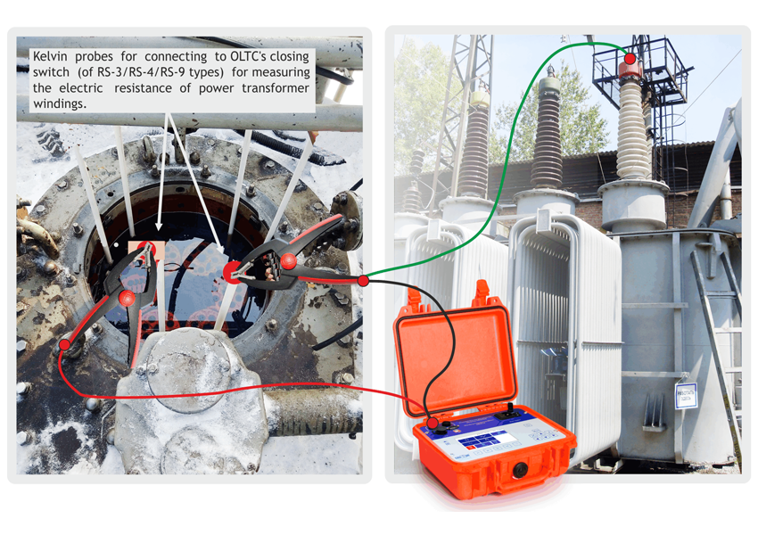
MIKO-9 milliohmmeter is a new development of the SKB EP Company. The instrument is designed for measuring the AC electric resistance in the inductance and inductance-free circuits in the range of 10 mkOhm ÷ 30 kOhm on currents of up to 10A. The milliohmmeter has a number of specific functions, including the option of simultaneous connection to three transformer phases, and measurement at automatic change-over; full automation of measurements; mode of transformer’s magnetic system demagnetization; ‘cooling test’ mode; mode of non-destructive testing of the OLTC devices (DRM-test method), and a number of other functions. More detailed information on the device is available at the Manufacturer’s websit.
Consider the method of failure search by dividing the electric circuit into four sections and measuring the electric resistance via the OLTC’s closing switch using MIKO-9 millliohmmeter and Kelvin probe [1]:
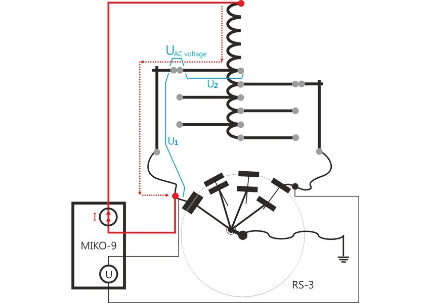
Section I: Measurement of electric resistance of the section from a branch of a teaser winding to the static contact of a closing switch (Fig. 2).
The measured section includes: electric resistance of cables connecting the branch of a teaser winding to the static contact of a closing switch; transient resistance between moving and static contacts of the selector; transient resistance of all the contact-type connections in the measured circuit.
Peculiar feature of the measurement diagram is that the test current is supplied to the HV transformer input, runs through its main winding, magnetizes its core thus reducing the transient process time. Then the current flows through the part of a teaser winding, via moving and static contacts of the selector.
Odd and even static contacts are points of recording the voltage drop. At such connection a part of the teaser winding and wires connecting a branch of the teaser winding with the selector and selector with the closing switch are used as extension of one of the potential wires of the MIKO-9 test cable.
For identifying the cause of exceeding the relative difference in winding resistance (2%), the absolute value of resistance (Rdefect), that makes 2% of the transformer’s winding resistance can be used as a criterion.
The rule for making a conclusion is as follows: the relative difference of the windings resistance exceeds 2% since the absolute difference of resistance from the branch to the closing switch exceeds Rdefect.
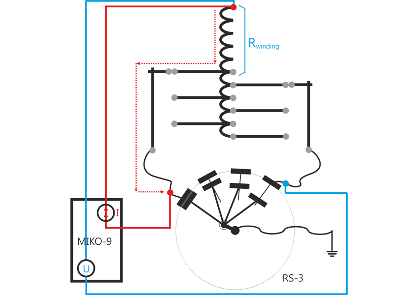
Section II: inspection of the section from HV input to the teaser winding start (Fig. 3).
Similarly to Section I, some transformer's circuits in this diagram are used as an extension of the potential circuit of a test cable. Similarly to Section I, for making a decision on the cause of exceeding the threshold value by the relative difference of resistance (2%), the allowable relative difference of resistance is recommended to be converted into the absolute value, and results of computed difference in the measured resistances shall be compared to this value.
Section III: Measurement of electric resistance of the closing switch contacts.
Break of wires connecting moving contacts with the neutral plate or burnt surfaces of the main contacts are among the problems related to the closing switch contacts. For checking the state of these elements the electric resistance is measured following the diagram given in Fig. 4.
Closing switches of the OLTC devices are manufactured as individual items whose performances (including electric resistance of its elements) depend on its type and version. Therefore, for excluding the electric resistance of the circuit belonging to the transformer (particularly, electric resistance from the closing switch to the Neutral input) from the results of measurements, two Kelvin probes must be used: one for connecting to the static contact of the closing switch, another one for connection to the Neutral plate contact.
Despite the fact that difference in electric resistances of the main contacts can be minimal, use of the closing switch proper operation criterion based on this difference is not correct. Closing switch contacts can be worn out in a similar way. The contacts state indicator in this case is the absolute value of transient resistance. Maximum electric resistance allowable for further operation of the main contacts is the responsibility of manufacturers of closing switches of this particular type.
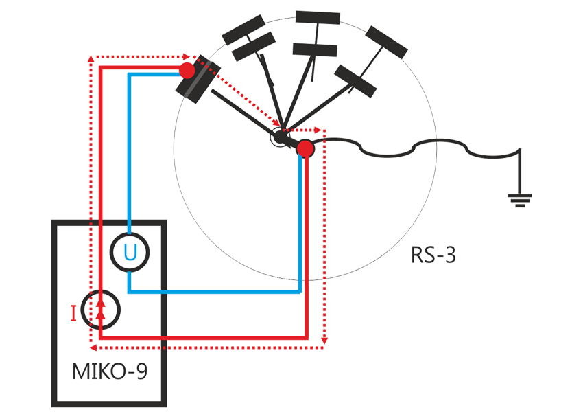
Section IV: Measurement of electric resistance from the Neutral plate of the closing switch to transformer's neutral input. The measured circuit includes cable resistance and resistance of contact-type connections.
Peculiar feature of diagnostics of this section lies in the fact that when computing the relative differences in resistances of windings from different phases, the resistance of this circuit is deducted, therefore, criteria for assessing its state used for Section I are not applicable here. For this reason, similarly to Section III, for making a decision on the state of this circuit, the absolute value of resistance shall be compared to allowances applicable to the inspected transformer type.
Thus, measurement of electric resistance using a non-conventional method allows:
- More accurate check of the results of measurements that allowed conclusion on excessing the threshold value (2%) of the relative difference in windings resistances since the share of critical area's resistance in the section’s resistance is higher than in the resistance of the entire circuit;
- Based on the information on the location of the critical area, preparatory measures can be undertaken prior to the transformer maintenance.
 Bookmark: #kelvinIn 2017 the SKP EP Company plans to commence production of Kelvin Probes for OLTC Devices that are designed for high-precision re-check of the relative deviation of electric resistance of three-phase power transformer windings from the rated value (2%), and for determination of the cause of the deviation.
The probe works with MIKO-9 device for measuring the windings resistance on the sections by connecting via static contacts of RS-3, RS-4 or RS-9 closing switch.
For more information on the described technique of diagnostics, on the new MIKO-9 milliohmmeter, and on the use of the Kelvin probes please contact our managers by tel.: +7(3952) 719-148.