 Русский
 Français
 Chinese
Comparison of SKB EP transformer OLTC diagnostic systems
One of the causes of OLTC damage are contactor and switching device malfunctions, contact burning of contactors, contactor mechanisms jamming, loss of mechanical strength of steel parts and paper-bakelite shaft.
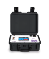
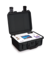
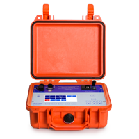
To identify the cause of OLTC fault and to automate the diagnostic process, SKB EP implements 2 specialized instruments for OLTC devices' diagnostic: PKR-2M and PKR-2, as well as 2 milli-ohmmeters: MIKO-9A and MIKO-8M(A) that has an auxiliary mode for OLTCs diagnostic.
| PKR-2М | PKR-2 | MIKO-9А | MIKO-8М(А) | |
|
|
|
|
|
| Electrical resistance measurement in the windings of power and instrument transformers |
|
|
|
|
|
Resistance measurement of internal contacts and connections of OLTC devices |
|
|
|
|
| Resistor type OLTC contactor switchover oscillography |
|
|
|
|
| Oscillogram recording by three phases simultaneously |
|
|
|
|
| Oscillogram recording phase by phase |
|
|
|
|
| "Demountable" diagnostic (with removing contactor tank) |
|
|
|
|
| Equipped with special probes for operation without complete or partial oil drain from contactor tank (on order) |
improved design for OLTCs of RS and RNT types with elastic grips |
improved design for OLTCs of RS and RNT types with elastic grips |
- | - |
| Non-demountable diagnostic of resistor type OLTCs (DRM method) |
|
Additional option - DRM-test mode can be activated upon request |
|
|
| Supplied with a special cable for secondary winding terminals short-circuiting |
standard and optional complete sets |
standard and optional complete sets |
optional |
optional |
| Measurement of test current when checking the contactor with non-demountable method | 1 - 4А |
1 - 4А |
до 10А | до 10А |
| Type of oscillogram recorded with the non-demountable DRM method | Three types of display, similar to the appearance of oscillograms recorded with direct connection to contactor |
Three types of display, similar to the appearance of oscillograms recorded with direct connection to contactor (after activation of DRM mode) |
Current oscillogram of contactor switchover process |
Current oscillogram of contactor switchover process |
| Method for generating/placing oscillograms in the measurement protocol | Automatic protocol generation in software for PC | Automatic protocol generation in software for PC | Transfer to cloud server on PC via USB cable | Transfer to cloud server on PC via USB cable |
| Maximum oscillogram recording time, min | 20 | 20 | 15 | 15 |
| Static checking of OLTC devices (when the drive shaft is rotated by the handle, the points of contacts closing/opening, voltages, currents and resistances on each tap are shown on the display) |
|
|
|
|
| Circular diagram recording of the resistor type OLTCs |
|
|
|
|
|
Circular diagram recording of the reactor type OLTCs |
|
|
|
|
| Circular diagrams recording simultaneously in three phases |
|
|
- | - |
| Circular diagrams recording phase by phase |
|
|
- | - |
| Graphical representation of full-fledged circular diagrams |
|
|
- | - |
| Table representation of data indicating the moment of switching of even and odd contacts (contactor and voter) |
in degrees for resistor OLTC devices and in revolutions for reactor OLTC devices |
in degrees for resistor OLTC devices and in revolutions for reactor OLTC devices |
- | - |
| Display size and type | color multi touch display 640 x 480 pixels | color multi touch display 640 x 480 pixels | TFT color multi touch display, 800 x 480 pixels | TFT color multi touch display, 800 x 480 pixels |
| Number of data transfer channels, pcs. | 2 (USB; USB host) |
1 (USB) |
2 (Bluetooth, USB) | 2 (Bluetooth, USB) |
| User Interface (set up before measurement) | 2-3 parameters must be set | 2-3 parameters must be set | 2-3 parameters must be set | 2-3 parameters must be set |
| Mains power supply |
|
|
|
|
| Power supply by built-in battery |
|
Additional option - a built-in battery is available on request |
|
MIKO-8MA modification |
| Dimensions, mm | 360х290х165 | 360х290х165 | 270х250х130 |
270х250х130 |
| Instrument weight, kg | 5,1 | 6,1 | 4,0 |
2,7 MIKO-8M modification 4,0 MIKO-8MA modification |
| Operating temperature range, ºC | -20 ÷ +40 | -20 ÷ +40 | -20 ÷ +55 |
-20 ÷ +55 |