Array
(
[ID] => 16537
[~ID] => 16537
[NAME] => Resistance measurement in inductive and non-inductive circuits in the range of 1 μΩ - 30 kΩ
[~NAME] => Resistance measurement in inductive and non-inductive circuits in the range of 1 μΩ - 30 kΩ
[IBLOCK_ID] => 102
[~IBLOCK_ID] => 102
[DETAIL_TEXT] =>
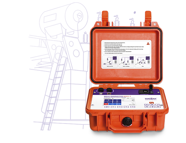
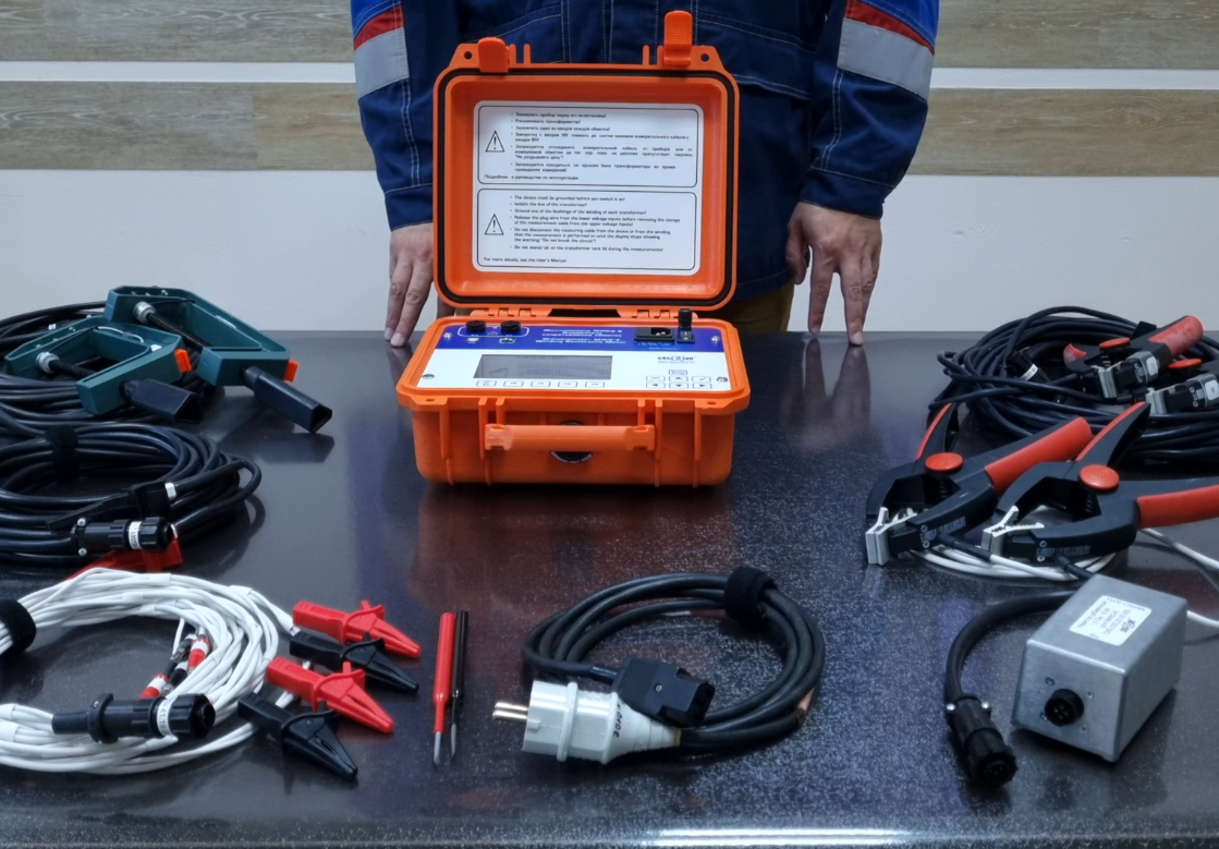
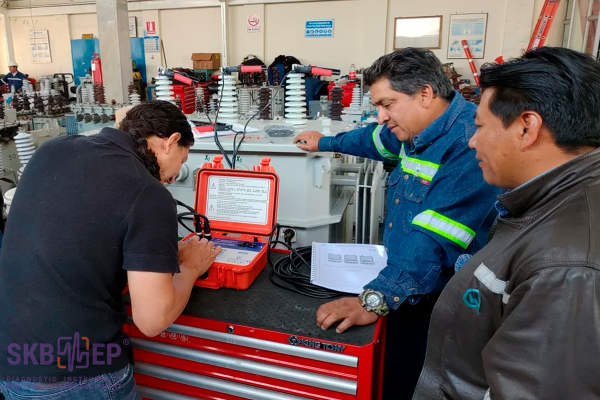
MIKO-9A milli-ohmmeter is developed to measure DC resistance in the range of 1 µΩ - 30 kΩ with test current up to 10 А, as well as to generate oscillograms of a switching contactor in the high-speed OLTC; it also provides for demagnetization and "Heat Run Test".
MIKO-9A diagnostic objects:
Windings of power and instrument transformers, windings of electric motors, generators, linear compensators and windings of other high-inductive equipment;
High-speed OLTCs;
Contacts of circuit breakers, resistors, buses and other non-inductive circuit;
Compensatory, current limiting and other resistors of high-voltage circuit breakers;
Сables.
Resistance measurement and test current ranges are automatically selected, it is possible to adjust the test current manually. The instrument ensures fully automated resistance measurement of highly inductive load and thermal EMF balancing in external circuit.
MIKO-9A implements specialized measurement modes for various configurations of 11 objects (resistive object, inductive object, voltage transformer, current transformer and power transformer, generator, motor, reactor, compensator, connection filter and magnet), taking into account their specific features. The user can select a standard object from the list, or create his own object.
The device automatically takes into account the configuration of the object for setting measurement modes.
Watch detailed video-reviews about MIKO-9A milli-ohmmeter up above ↑ or on the video page.
[~DETAIL_TEXT] =>
MIKO-9A milli-ohmmeter is developed to measure DC resistance in the range of 1 µΩ - 30 kΩ with test current up to 10 А, as well as to generate oscillograms of a switching contactor in the high-speed OLTC; it also provides for demagnetization and "Heat Run Test".
MIKO-9A diagnostic objects:
Windings of power and instrument transformers, windings of electric motors, generators, linear compensators and windings of other high-inductive equipment;
High-speed OLTCs;
Contacts of circuit breakers, resistors, buses and other non-inductive circuit;
Compensatory, current limiting and other resistors of high-voltage circuit breakers;
Сables.
Resistance measurement and test current ranges are automatically selected, it is possible to adjust the test current manually. The instrument ensures fully automated resistance measurement of highly inductive load and thermal EMF balancing in external circuit.
MIKO-9A implements specialized measurement modes for various configurations of 11 objects (resistive object, inductive object, voltage transformer, current transformer and power transformer, generator, motor, reactor, compensator, connection filter and magnet), taking into account their specific features. The user can select a standard object from the list, or create his own object.
The device automatically takes into account the configuration of the object for setting measurement modes.
Watch detailed video-reviews about MIKO-9A milli-ohmmeter up above ↑ or on the video page.
[SORT] => 10
[~SORT] => 10
[DETAIL_TEXT_TYPE] => html
[~DETAIL_TEXT_TYPE] => html
[PROPERTIES] => Array
(
[PREVIEW_ICON] => Array
(
[ID] => 310
[TIMESTAMP_X] => 2019-11-18 14:18:31
[IBLOCK_ID] => 102
[NAME] => Иконка для анонса
[ACTIVE] => Y
[SORT] => 500
[CODE] => PREVIEW_ICON
[DEFAULT_VALUE] =>
[PROPERTY_TYPE] => F
[ROW_COUNT] => 1
[COL_COUNT] => 50
[LIST_TYPE] => L
[MULTIPLE] => N
[XML_ID] => 28
[FILE_TYPE] => jpg, png, jpeg
[MULTIPLE_CNT] => 5
[TMP_ID] =>
[LINK_IBLOCK_ID] => 0
[WITH_DESCRIPTION] => N
[SEARCHABLE] => N
[FILTRABLE] => N
[IS_REQUIRED] => Y
[VERSION] => 1
[USER_TYPE] =>
[USER_TYPE_SETTINGS] =>
[HINT] =>
[PROPERTY_VALUE_ID] => 32685
[VALUE] => 20661
[DESCRIPTION] =>
[VALUE_ENUM] =>
[VALUE_XML_ID] =>
[VALUE_SORT] =>
[~VALUE] => 20661
[~DESCRIPTION] =>
[~NAME] => Иконка для анонса
[~DEFAULT_VALUE] =>
)
[DETAIL_ICON] => Array
(
[ID] => 311
[TIMESTAMP_X] => 2019-11-18 14:18:31
[IBLOCK_ID] => 102
[NAME] => Иконка для описания
[ACTIVE] => Y
[SORT] => 500
[CODE] => DETAIL_ICON
[DEFAULT_VALUE] =>
[PROPERTY_TYPE] => F
[ROW_COUNT] => 1
[COL_COUNT] => 50
[LIST_TYPE] => L
[MULTIPLE] => N
[XML_ID] => 29
[FILE_TYPE] => jpg, png, jpeg
[MULTIPLE_CNT] => 5
[TMP_ID] =>
[LINK_IBLOCK_ID] => 0
[WITH_DESCRIPTION] => N
[SEARCHABLE] => N
[FILTRABLE] => N
[IS_REQUIRED] => Y
[VERSION] => 1
[USER_TYPE] =>
[USER_TYPE_SETTINGS] =>
[HINT] =>
[PROPERTY_VALUE_ID] => 32686
[VALUE] => 20662
[DESCRIPTION] =>
[VALUE_ENUM] =>
[VALUE_XML_ID] =>
[VALUE_SORT] =>
[~VALUE] => 20662
[~DESCRIPTION] =>
[~NAME] => Иконка для описания
[~DEFAULT_VALUE] =>
)
[MORE_PHOTO] => Array
(
[ID] => 312
[TIMESTAMP_X] => 2019-11-18 14:18:31
[IBLOCK_ID] => 102
[NAME] => Фотографии
[ACTIVE] => Y
[SORT] => 500
[CODE] => MORE_PHOTO
[DEFAULT_VALUE] =>
[PROPERTY_TYPE] => F
[ROW_COUNT] => 1
[COL_COUNT] => 50
[LIST_TYPE] => L
[MULTIPLE] => Y
[XML_ID] => 30
[FILE_TYPE] => jpg, png, jpeg
[MULTIPLE_CNT] => 5
[TMP_ID] =>
[LINK_IBLOCK_ID] => 0
[WITH_DESCRIPTION] => Y
[SEARCHABLE] => N
[FILTRABLE] => N
[IS_REQUIRED] => N
[VERSION] => 1
[USER_TYPE] =>
[USER_TYPE_SETTINGS] =>
[HINT] =>
[PROPERTY_VALUE_ID] =>
[VALUE] =>
[DESCRIPTION] =>
[VALUE_ENUM] =>
[VALUE_XML_ID] =>
[VALUE_SORT] =>
[~VALUE] =>
[~DESCRIPTION] =>
[~NAME] => Фотографии
[~DEFAULT_VALUE] =>
)
)
)
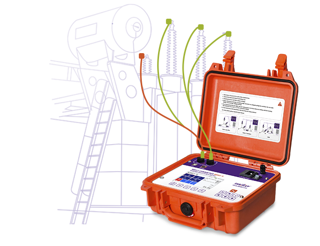
Depending on the object type, special measurement modes can be selected. For a resistive object, the modes are completely similar to the MIKO-8М(А), and for an inductive object, in addition to the two modes MANUAL and AUTO 1Ph, you can select AUTO 3Ph and 2 WINDINGS.
AUTO 3Ph makes it possible to simultaneously connect to three phases of the transformer and take measurements with automatic switching between them. This mode reduces the amount of reconnecting to/from the object under test.
AUTO 1Ph and AUTO 3Ph modes have SKB EP patented automatic measurement method that guarantees results with the highest accuracy in challenging electromagnetic environments.
During the measurement process, the device calculates the estimated resistance of the object, excluding the need to select a measurement subrange, and sets the max power measurement current for the measured circuit. This ensures measurement accuracy in substation interference conditions approaches laboratory conditions.
A special measurement signal delivery mode also reduces the current and voltage stabilization time, reducing the overall measurement time.
[~DETAIL_TEXT] =>
Depending on the object type, special measurement modes can be selected. For a resistive object, the modes are completely similar to the MIKO-8М(А), and for an inductive object, in addition to the two modes MANUAL and AUTO 1Ph, you can select AUTO 3Ph and 2 WINDINGS.
AUTO 3Ph makes it possible to simultaneously connect to three phases of the transformer and take measurements with automatic switching between them. This mode reduces the amount of reconnecting to/from the object under test.
AUTO 1Ph and AUTO 3Ph modes have SKB EP patented automatic measurement method that guarantees results with the highest accuracy in challenging electromagnetic environments.
During the measurement process, the device calculates the estimated resistance of the object, excluding the need to select a measurement subrange, and sets the max power measurement current for the measured circuit. This ensures measurement accuracy in substation interference conditions approaches laboratory conditions.
A special measurement signal delivery mode also reduces the current and voltage stabilization time, reducing the overall measurement time.
[SORT] => 20
[~SORT] => 20
[DETAIL_TEXT_TYPE] => html
[~DETAIL_TEXT_TYPE] => html
[PROPERTIES] => Array
(
[PREVIEW_ICON] => Array
(
[ID] => 310
[TIMESTAMP_X] => 2019-11-18 14:18:31
[IBLOCK_ID] => 102
[NAME] => Иконка для анонса
[ACTIVE] => Y
[SORT] => 500
[CODE] => PREVIEW_ICON
[DEFAULT_VALUE] =>
[PROPERTY_TYPE] => F
[ROW_COUNT] => 1
[COL_COUNT] => 50
[LIST_TYPE] => L
[MULTIPLE] => N
[XML_ID] => 28
[FILE_TYPE] => jpg, png, jpeg
[MULTIPLE_CNT] => 5
[TMP_ID] =>
[LINK_IBLOCK_ID] => 0
[WITH_DESCRIPTION] => N
[SEARCHABLE] => N
[FILTRABLE] => N
[IS_REQUIRED] => Y
[VERSION] => 1
[USER_TYPE] =>
[USER_TYPE_SETTINGS] =>
[HINT] =>
[PROPERTY_VALUE_ID] => 32687
[VALUE] => 20664
[DESCRIPTION] =>
[VALUE_ENUM] =>
[VALUE_XML_ID] =>
[VALUE_SORT] =>
[~VALUE] => 20664
[~DESCRIPTION] =>
[~NAME] => Иконка для анонса
[~DEFAULT_VALUE] =>
)
[DETAIL_ICON] => Array
(
[ID] => 311
[TIMESTAMP_X] => 2019-11-18 14:18:31
[IBLOCK_ID] => 102
[NAME] => Иконка для описания
[ACTIVE] => Y
[SORT] => 500
[CODE] => DETAIL_ICON
[DEFAULT_VALUE] =>
[PROPERTY_TYPE] => F
[ROW_COUNT] => 1
[COL_COUNT] => 50
[LIST_TYPE] => L
[MULTIPLE] => N
[XML_ID] => 29
[FILE_TYPE] => jpg, png, jpeg
[MULTIPLE_CNT] => 5
[TMP_ID] =>
[LINK_IBLOCK_ID] => 0
[WITH_DESCRIPTION] => N
[SEARCHABLE] => N
[FILTRABLE] => N
[IS_REQUIRED] => Y
[VERSION] => 1
[USER_TYPE] =>
[USER_TYPE_SETTINGS] =>
[HINT] =>
[PROPERTY_VALUE_ID] => 32688
[VALUE] => 20665
[DESCRIPTION] =>
[VALUE_ENUM] =>
[VALUE_XML_ID] =>
[VALUE_SORT] =>
[~VALUE] => 20665
[~DESCRIPTION] =>
[~NAME] => Иконка для описания
[~DEFAULT_VALUE] =>
)
[MORE_PHOTO] => Array
(
[ID] => 312
[TIMESTAMP_X] => 2019-11-18 14:18:31
[IBLOCK_ID] => 102
[NAME] => Фотографии
[ACTIVE] => Y
[SORT] => 500
[CODE] => MORE_PHOTO
[DEFAULT_VALUE] =>
[PROPERTY_TYPE] => F
[ROW_COUNT] => 1
[COL_COUNT] => 50
[LIST_TYPE] => L
[MULTIPLE] => Y
[XML_ID] => 30
[FILE_TYPE] => jpg, png, jpeg
[MULTIPLE_CNT] => 5
[TMP_ID] =>
[LINK_IBLOCK_ID] => 0
[WITH_DESCRIPTION] => Y
[SEARCHABLE] => N
[FILTRABLE] => N
[IS_REQUIRED] => N
[VERSION] => 1
[USER_TYPE] =>
[USER_TYPE_SETTINGS] =>
[HINT] =>
[PROPERTY_VALUE_ID] =>
[VALUE] =>
[DESCRIPTION] =>
[VALUE_ENUM] =>
[VALUE_XML_ID] =>
[VALUE_SORT] =>
[~VALUE] =>
[~DESCRIPTION] =>
[~NAME] => Фотографии
[~DEFAULT_VALUE] =>
)
)
)
Depending on the object type, special measurement modes can be selected. For a resistive object, the modes are completely similar to the MIKO-8М(А) device, and for an inductive object, in addition to the three modes MANUAL, AUTO 1Ph and AUTO 3Ph, you can choose 2 WINDINGS mode.
This mode enables resistance measurement simultaneously on two windings, and guarantees a quick and reliable measurement of the electrical resistance of heavy power transformers, in particular, with secondary windings delta connected when using traditional methods does not give a stable result.
The device indicates which phases should be connected to accelerate the measurement process, taking into account the distribution of magnetic fluxes in the magnetic circuit. In addition, the simultaneous measurement of two windings reduces the total number of test cable reconnection from 6 to 3.
[~DETAIL_TEXT] =>
Depending on the object type, special measurement modes can be selected. For a resistive object, the modes are completely similar to the MIKO-8М(А) device, and for an inductive object, in addition to the three modes MANUAL, AUTO 1Ph and AUTO 3Ph, you can choose 2 WINDINGS mode.
This mode enables resistance measurement simultaneously on two windings, and guarantees a quick and reliable measurement of the electrical resistance of heavy power transformers, in particular, with secondary windings delta connected when using traditional methods does not give a stable result.
The device indicates which phases should be connected to accelerate the measurement process, taking into account the distribution of magnetic fluxes in the magnetic circuit. In addition, the simultaneous measurement of two windings reduces the total number of test cable reconnection from 6 to 3.
[SORT] => 30
[~SORT] => 30
[DETAIL_TEXT_TYPE] => html
[~DETAIL_TEXT_TYPE] => html
[PROPERTIES] => Array
(
[PREVIEW_ICON] => Array
(
[ID] => 310
[TIMESTAMP_X] => 2019-11-18 14:18:31
[IBLOCK_ID] => 102
[NAME] => Иконка для анонса
[ACTIVE] => Y
[SORT] => 500
[CODE] => PREVIEW_ICON
[DEFAULT_VALUE] =>
[PROPERTY_TYPE] => F
[ROW_COUNT] => 1
[COL_COUNT] => 50
[LIST_TYPE] => L
[MULTIPLE] => N
[XML_ID] => 28
[FILE_TYPE] => jpg, png, jpeg
[MULTIPLE_CNT] => 5
[TMP_ID] =>
[LINK_IBLOCK_ID] => 0
[WITH_DESCRIPTION] => N
[SEARCHABLE] => N
[FILTRABLE] => N
[IS_REQUIRED] => Y
[VERSION] => 1
[USER_TYPE] =>
[USER_TYPE_SETTINGS] =>
[HINT] =>
[PROPERTY_VALUE_ID] => 32689
[VALUE] => 20667
[DESCRIPTION] =>
[VALUE_ENUM] =>
[VALUE_XML_ID] =>
[VALUE_SORT] =>
[~VALUE] => 20667
[~DESCRIPTION] =>
[~NAME] => Иконка для анонса
[~DEFAULT_VALUE] =>
)
[DETAIL_ICON] => Array
(
[ID] => 311
[TIMESTAMP_X] => 2019-11-18 14:18:31
[IBLOCK_ID] => 102
[NAME] => Иконка для описания
[ACTIVE] => Y
[SORT] => 500
[CODE] => DETAIL_ICON
[DEFAULT_VALUE] =>
[PROPERTY_TYPE] => F
[ROW_COUNT] => 1
[COL_COUNT] => 50
[LIST_TYPE] => L
[MULTIPLE] => N
[XML_ID] => 29
[FILE_TYPE] => jpg, png, jpeg
[MULTIPLE_CNT] => 5
[TMP_ID] =>
[LINK_IBLOCK_ID] => 0
[WITH_DESCRIPTION] => N
[SEARCHABLE] => N
[FILTRABLE] => N
[IS_REQUIRED] => Y
[VERSION] => 1
[USER_TYPE] =>
[USER_TYPE_SETTINGS] =>
[HINT] =>
[PROPERTY_VALUE_ID] => 32690
[VALUE] => 20668
[DESCRIPTION] =>
[VALUE_ENUM] =>
[VALUE_XML_ID] =>
[VALUE_SORT] =>
[~VALUE] => 20668
[~DESCRIPTION] =>
[~NAME] => Иконка для описания
[~DEFAULT_VALUE] =>
)
[MORE_PHOTO] => Array
(
[ID] => 312
[TIMESTAMP_X] => 2019-11-18 14:18:31
[IBLOCK_ID] => 102
[NAME] => Фотографии
[ACTIVE] => Y
[SORT] => 500
[CODE] => MORE_PHOTO
[DEFAULT_VALUE] =>
[PROPERTY_TYPE] => F
[ROW_COUNT] => 1
[COL_COUNT] => 50
[LIST_TYPE] => L
[MULTIPLE] => Y
[XML_ID] => 30
[FILE_TYPE] => jpg, png, jpeg
[MULTIPLE_CNT] => 5
[TMP_ID] =>
[LINK_IBLOCK_ID] => 0
[WITH_DESCRIPTION] => Y
[SEARCHABLE] => N
[FILTRABLE] => N
[IS_REQUIRED] => N
[VERSION] => 1
[USER_TYPE] =>
[USER_TYPE_SETTINGS] =>
[HINT] =>
[PROPERTY_VALUE_ID] =>
[VALUE] =>
[DESCRIPTION] =>
[VALUE_ENUM] =>
[VALUE_XML_ID] =>
[VALUE_SORT] =>
[~VALUE] =>
[~DESCRIPTION] =>
[~NAME] => Фотографии
[~DEFAULT_VALUE] =>
)
)
)
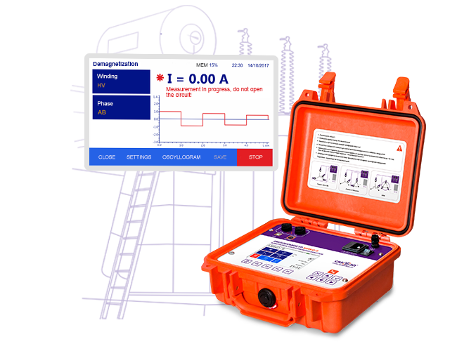
Demagnetization mode is designed to eliminate the remnant magnetism of the transformer magnetic core. It is compulsory to be made before open-circuit test, short-circuit loss measurement, transformation ratio measurement, etc.
The instrument can be used for demagnetization of both single-phase and three-phase transformers. Magnetic core demagnetization requires alternating current applied to the corresponding winding bidirectionally.
Demagnetization is performed automatically. Current decreases with each direction change. Each rod of a three-phase transformer is subjected to demagnetization.
Current change is at the same time displayed in a graph form to control demagnetization accuracy. Demagnetization stops automatically when the current reaches threshold value or upon the user’s command
[~DETAIL_TEXT] =>
Demagnetization mode is designed to eliminate the remnant magnetism of the transformer magnetic core. It is compulsory to be made before open-circuit test, short-circuit loss measurement, transformation ratio measurement, etc.
The instrument can be used for demagnetization of both single-phase and three-phase transformers. Magnetic core demagnetization requires alternating current applied to the corresponding winding bidirectionally.
Demagnetization is performed automatically. Current decreases with each direction change. Each rod of a three-phase transformer is subjected to demagnetization.
Current change is at the same time displayed in a graph form to control demagnetization accuracy. Demagnetization stops automatically when the current reaches threshold value or upon the user’s command
[SORT] => 40
[~SORT] => 40
[DETAIL_TEXT_TYPE] => html
[~DETAIL_TEXT_TYPE] => html
[PROPERTIES] => Array
(
[PREVIEW_ICON] => Array
(
[ID] => 310
[TIMESTAMP_X] => 2019-11-18 14:18:31
[IBLOCK_ID] => 102
[NAME] => Иконка для анонса
[ACTIVE] => Y
[SORT] => 500
[CODE] => PREVIEW_ICON
[DEFAULT_VALUE] =>
[PROPERTY_TYPE] => F
[ROW_COUNT] => 1
[COL_COUNT] => 50
[LIST_TYPE] => L
[MULTIPLE] => N
[XML_ID] => 28
[FILE_TYPE] => jpg, png, jpeg
[MULTIPLE_CNT] => 5
[TMP_ID] =>
[LINK_IBLOCK_ID] => 0
[WITH_DESCRIPTION] => N
[SEARCHABLE] => N
[FILTRABLE] => N
[IS_REQUIRED] => Y
[VERSION] => 1
[USER_TYPE] =>
[USER_TYPE_SETTINGS] =>
[HINT] =>
[PROPERTY_VALUE_ID] => 32691
[VALUE] => 20670
[DESCRIPTION] =>
[VALUE_ENUM] =>
[VALUE_XML_ID] =>
[VALUE_SORT] =>
[~VALUE] => 20670
[~DESCRIPTION] =>
[~NAME] => Иконка для анонса
[~DEFAULT_VALUE] =>
)
[DETAIL_ICON] => Array
(
[ID] => 311
[TIMESTAMP_X] => 2019-11-18 14:18:31
[IBLOCK_ID] => 102
[NAME] => Иконка для описания
[ACTIVE] => Y
[SORT] => 500
[CODE] => DETAIL_ICON
[DEFAULT_VALUE] =>
[PROPERTY_TYPE] => F
[ROW_COUNT] => 1
[COL_COUNT] => 50
[LIST_TYPE] => L
[MULTIPLE] => N
[XML_ID] => 29
[FILE_TYPE] => jpg, png, jpeg
[MULTIPLE_CNT] => 5
[TMP_ID] =>
[LINK_IBLOCK_ID] => 0
[WITH_DESCRIPTION] => N
[SEARCHABLE] => N
[FILTRABLE] => N
[IS_REQUIRED] => Y
[VERSION] => 1
[USER_TYPE] =>
[USER_TYPE_SETTINGS] =>
[HINT] =>
[PROPERTY_VALUE_ID] => 32692
[VALUE] => 20671
[DESCRIPTION] =>
[VALUE_ENUM] =>
[VALUE_XML_ID] =>
[VALUE_SORT] =>
[~VALUE] => 20671
[~DESCRIPTION] =>
[~NAME] => Иконка для описания
[~DEFAULT_VALUE] =>
)
[MORE_PHOTO] => Array
(
[ID] => 312
[TIMESTAMP_X] => 2019-11-18 14:18:31
[IBLOCK_ID] => 102
[NAME] => Фотографии
[ACTIVE] => Y
[SORT] => 500
[CODE] => MORE_PHOTO
[DEFAULT_VALUE] =>
[PROPERTY_TYPE] => F
[ROW_COUNT] => 1
[COL_COUNT] => 50
[LIST_TYPE] => L
[MULTIPLE] => Y
[XML_ID] => 30
[FILE_TYPE] => jpg, png, jpeg
[MULTIPLE_CNT] => 5
[TMP_ID] =>
[LINK_IBLOCK_ID] => 0
[WITH_DESCRIPTION] => Y
[SEARCHABLE] => N
[FILTRABLE] => N
[IS_REQUIRED] => N
[VERSION] => 1
[USER_TYPE] =>
[USER_TYPE_SETTINGS] =>
[HINT] =>
[PROPERTY_VALUE_ID] =>
[VALUE] =>
[DESCRIPTION] =>
[VALUE_ENUM] =>
[VALUE_XML_ID] =>
[VALUE_SORT] =>
[~VALUE] =>
[~DESCRIPTION] =>
[~NAME] => Фотографии
[~DEFAULT_VALUE] =>
)
)
)
Array
(
[ID] => 16541
[~ID] => 16541
[NAME] => Non-demountable estimation of the OLTCs (DRM test)
[~NAME] => Non-demountable estimation of the OLTCs (DRM test)
[IBLOCK_ID] => 102
[~IBLOCK_ID] => 102
[DETAIL_TEXT] =>
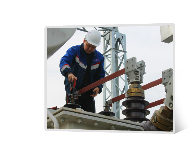
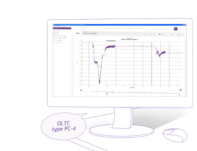
OLTC non-demountable check mode allows the user to assess the state of the switching OLTC equipment with current limiting resistors without removing the contactor tank cover.
This mode involves measuring of instant test current values. Test current firstly passes through the transformer winding and then through OLTC contacts at switching from one tap to another. The DRM graph is built on the basis of the measurement results and shows current change during tap changing. This graph enables to check tap changing time and general object state.
Analysis of the acquired graphs enables not only to sort out OLTC by fault-free/faulty criteria but also to define the nature of the defect eliminating the opening of fault-free OLTCs. Milli-ohmmeter mode and DRM test complement each other and provide the user comprehensive information about the transformer state.
[~DETAIL_TEXT] =>
OLTC non-demountable check mode allows the user to assess the state of the switching OLTC equipment with current limiting resistors without removing the contactor tank cover.
This mode involves measuring of instant test current values. Test current firstly passes through the transformer winding and then through OLTC contacts at switching from one tap to another. The DRM graph is built on the basis of the measurement results and shows current change during tap changing. This graph enables to check tap changing time and general object state.
Analysis of the acquired graphs enables not only to sort out OLTC by fault-free/faulty criteria but also to define the nature of the defect eliminating the opening of fault-free OLTCs. Milli-ohmmeter mode and DRM test complement each other and provide the user comprehensive information about the transformer state.
[SORT] => 50
[~SORT] => 50
[DETAIL_TEXT_TYPE] => html
[~DETAIL_TEXT_TYPE] => html
[PROPERTIES] => Array
(
[PREVIEW_ICON] => Array
(
[ID] => 310
[TIMESTAMP_X] => 2019-11-18 14:18:31
[IBLOCK_ID] => 102
[NAME] => Иконка для анонса
[ACTIVE] => Y
[SORT] => 500
[CODE] => PREVIEW_ICON
[DEFAULT_VALUE] =>
[PROPERTY_TYPE] => F
[ROW_COUNT] => 1
[COL_COUNT] => 50
[LIST_TYPE] => L
[MULTIPLE] => N
[XML_ID] => 28
[FILE_TYPE] => jpg, png, jpeg
[MULTIPLE_CNT] => 5
[TMP_ID] =>
[LINK_IBLOCK_ID] => 0
[WITH_DESCRIPTION] => N
[SEARCHABLE] => N
[FILTRABLE] => N
[IS_REQUIRED] => Y
[VERSION] => 1
[USER_TYPE] =>
[USER_TYPE_SETTINGS] =>
[HINT] =>
[PROPERTY_VALUE_ID] => 32693
[VALUE] => 20673
[DESCRIPTION] =>
[VALUE_ENUM] =>
[VALUE_XML_ID] =>
[VALUE_SORT] =>
[~VALUE] => 20673
[~DESCRIPTION] =>
[~NAME] => Иконка для анонса
[~DEFAULT_VALUE] =>
)
[DETAIL_ICON] => Array
(
[ID] => 311
[TIMESTAMP_X] => 2019-11-18 14:18:31
[IBLOCK_ID] => 102
[NAME] => Иконка для описания
[ACTIVE] => Y
[SORT] => 500
[CODE] => DETAIL_ICON
[DEFAULT_VALUE] =>
[PROPERTY_TYPE] => F
[ROW_COUNT] => 1
[COL_COUNT] => 50
[LIST_TYPE] => L
[MULTIPLE] => N
[XML_ID] => 29
[FILE_TYPE] => jpg, png, jpeg
[MULTIPLE_CNT] => 5
[TMP_ID] =>
[LINK_IBLOCK_ID] => 0
[WITH_DESCRIPTION] => N
[SEARCHABLE] => N
[FILTRABLE] => N
[IS_REQUIRED] => Y
[VERSION] => 1
[USER_TYPE] =>
[USER_TYPE_SETTINGS] =>
[HINT] =>
[PROPERTY_VALUE_ID] => 32694
[VALUE] => 20674
[DESCRIPTION] =>
[VALUE_ENUM] =>
[VALUE_XML_ID] =>
[VALUE_SORT] =>
[~VALUE] => 20674
[~DESCRIPTION] =>
[~NAME] => Иконка для описания
[~DEFAULT_VALUE] =>
)
[MORE_PHOTO] => Array
(
[ID] => 312
[TIMESTAMP_X] => 2019-11-18 14:18:31
[IBLOCK_ID] => 102
[NAME] => Фотографии
[ACTIVE] => Y
[SORT] => 500
[CODE] => MORE_PHOTO
[DEFAULT_VALUE] =>
[PROPERTY_TYPE] => F
[ROW_COUNT] => 1
[COL_COUNT] => 50
[LIST_TYPE] => L
[MULTIPLE] => Y
[XML_ID] => 30
[FILE_TYPE] => jpg, png, jpeg
[MULTIPLE_CNT] => 5
[TMP_ID] =>
[LINK_IBLOCK_ID] => 0
[WITH_DESCRIPTION] => Y
[SEARCHABLE] => N
[FILTRABLE] => N
[IS_REQUIRED] => N
[VERSION] => 1
[USER_TYPE] =>
[USER_TYPE_SETTINGS] =>
[HINT] =>
[PROPERTY_VALUE_ID] =>
[VALUE] =>
[DESCRIPTION] =>
[VALUE_ENUM] =>
[VALUE_XML_ID] =>
[VALUE_SORT] =>
[~VALUE] =>
[~DESCRIPTION] =>
[~NAME] => Фотографии
[~DEFAULT_VALUE] =>
)
)
)
Array
(
    [ID] => 16542
    [~ID] => 16542
    [NAME] => Heat run test
    [~NAME] => Heat run test
    [IBLOCK_ID] => 102
    [~IBLOCK_ID] => 102
    [DETAIL_TEXT] =>
	 The test is performed by continuous measurement and periodic result saving of the transformer winding resistance (recalculated to t°) during the cooling process of the winding.


	 To receive the most reliable information about the max winding t° the user should connect the instrument to the winding and start the measurement immediately after the transformer heating is stopped.


	 Before the start of the measurement process the user has to specify winding, phase, max measurement duration, frequency of measurement results saving, winding resistance and temperature under normal conditions. Correlation between the winding temperature and the time can be represented in tabular or graphical form. The time is counted from the moment of the measurement start. Heat run test stops automatically on expiry of preset test duration or manually by the user.

    [~DETAIL_TEXT] =>
	 The test is performed by continuous measurement and periodic result saving of the transformer winding resistance (recalculated to t°) during the cooling process of the winding.


	 To receive the most reliable information about the max winding t° the user should connect the instrument to the winding and start the measurement immediately after the transformer heating is stopped.


	 Before the start of the measurement process the user has to specify winding, phase, max measurement duration, frequency of measurement results saving, winding resistance and temperature under normal conditions. Correlation between the winding temperature and the time can be represented in tabular or graphical form. The time is counted from the moment of the measurement start. Heat run test stops automatically on expiry of preset test duration or manually by the user.

    [SORT] => 60
    [~SORT] => 60
    [DETAIL_TEXT_TYPE] => html
    [~DETAIL_TEXT_TYPE] => html
    [PROPERTIES] => Array
        (
            [PREVIEW_ICON] => Array
                (
                    [ID] => 310
                    [TIMESTAMP_X] => 2019-11-18 14:18:31
                    [IBLOCK_ID] => 102
                    [NAME] => Иконка для анонса
                    [ACTIVE] => Y
                    [SORT] => 500
                    [CODE] => PREVIEW_ICON
                    [DEFAULT_VALUE] =>
                    [PROPERTY_TYPE] => F
                    [ROW_COUNT] => 1
                    [COL_COUNT] => 50
                    [LIST_TYPE] => L
                    [MULTIPLE] => N
                    [XML_ID] => 28
                    [FILE_TYPE] => jpg, png, jpeg
                    [MULTIPLE_CNT] => 5
                    [TMP_ID] =>
                    [LINK_IBLOCK_ID] => 0
                    [WITH_DESCRIPTION] => N
                    [SEARCHABLE] => N
                    [FILTRABLE] => N
                    [IS_REQUIRED] => Y
                    [VERSION] => 1
                    [USER_TYPE] =>
                    [USER_TYPE_SETTINGS] =>
                    [HINT] =>
                    [PROPERTY_VALUE_ID] => 32695
                    [VALUE] => 20676
                    [DESCRIPTION] =>
                    [VALUE_ENUM] =>
                    [VALUE_XML_ID] =>
                    [VALUE_SORT] =>
                    [~VALUE] => 20676
                    [~DESCRIPTION] =>
                    [~NAME] => Иконка для анонса
                    [~DEFAULT_VALUE] =>
                )

            [DETAIL_ICON] => Array
                (
                    [ID] => 311
                    [TIMESTAMP_X] => 2019-11-18 14:18:31
                    [IBLOCK_ID] => 102
                    [NAME] => Иконка для описания
                    [ACTIVE] => Y
                    [SORT] => 500
                    [CODE] => DETAIL_ICON
                    [DEFAULT_VALUE] =>
                    [PROPERTY_TYPE] => F
                    [ROW_COUNT] => 1
                    [COL_COUNT] => 50
                    [LIST_TYPE] => L
                    [MULTIPLE] => N
                    [XML_ID] => 29
                    [FILE_TYPE] => jpg, png, jpeg
                    [MULTIPLE_CNT] => 5
                    [TMP_ID] =>
                    [LINK_IBLOCK_ID] => 0
                    [WITH_DESCRIPTION] => N
                    [SEARCHABLE] => N
                    [FILTRABLE] => N
                    [IS_REQUIRED] => Y
                    [VERSION] => 1
                    [USER_TYPE] =>
                    [USER_TYPE_SETTINGS] =>
                    [HINT] =>
                    [PROPERTY_VALUE_ID] => 32696
                    [VALUE] => 20677
                    [DESCRIPTION] =>
                    [VALUE_ENUM] =>
                    [VALUE_XML_ID] =>
                    [VALUE_SORT] =>
                    [~VALUE] => 20677
                    [~DESCRIPTION] =>
                    [~NAME] => Иконка для описания
                    [~DEFAULT_VALUE] =>
                )

            [MORE_PHOTO] => Array
                (
                    [ID] => 312
                    [TIMESTAMP_X] => 2019-11-18 14:18:31
                    [IBLOCK_ID] => 102
                    [NAME] => Фотографии
                    [ACTIVE] => Y
                    [SORT] => 500
                    [CODE] => MORE_PHOTO
                    [DEFAULT_VALUE] =>
                    [PROPERTY_TYPE] => F
                    [ROW_COUNT] => 1
                    [COL_COUNT] => 50
                    [LIST_TYPE] => L
                    [MULTIPLE] => Y
                    [XML_ID] => 30
                    [FILE_TYPE] => jpg, png, jpeg
                    [MULTIPLE_CNT] => 5
                    [TMP_ID] =>
                    [LINK_IBLOCK_ID] => 0
                    [WITH_DESCRIPTION] => Y
                    [SEARCHABLE] => N
                    [FILTRABLE] => N
                    [IS_REQUIRED] => N
                    [VERSION] => 1
                    [USER_TYPE] =>
                    [USER_TYPE_SETTINGS] =>
                    [HINT] =>
                    [PROPERTY_VALUE_ID] =>
                    [VALUE] =>
                    [DESCRIPTION] =>
                    [VALUE_ENUM] =>
                    [VALUE_XML_ID] =>
                    [VALUE_SORT] =>
                    [~VALUE] =>
                    [~DESCRIPTION] =>
                    [~NAME] => Фотографии
                    [~DEFAULT_VALUE] =>
                )

        )

)
Array
(
[ID] => 16543
[~ID] => 16543
[NAME] => Various auto calculations and non-volatile memory
[~NAME] => Various auto calculations and non-volatile memory
[IBLOCK_ID] => 102
[~IBLOCK_ID] => 102
[DETAIL_TEXT] =>
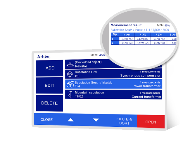
MIKO-9A has a built-in archive of up to 1,000 measurements for viewing, copying or deleting data. And due to the possibility of choosing an object at the measurement stage, the results are presented more systematically. This facilitates interaction with the archive.
The group of MIKO-7M(A), MIKO-8M(A) and MIKO-9A instruments has a number of automatic recalculation functions:
Auto δ calculation of Rphasebetween one another.
Auto conversion of Rlinear to Rphase. Linear windings are Delta or Star without neutral connected.
Auto correction of R measured at t° to R at t°p taking into account the winding material.
Auto δ calculation between Rcorrected and Rp.
Auto calculation of t° by its R.
Measurement results are automatically saved to the non-volatile memory and can be later processed by special software on PC or transmitted via Bluetooth to a smartphone.
[~DETAIL_TEXT] =>
MIKO-9A has a built-in archive of up to 1,000 measurements for viewing, copying or deleting data. And due to the possibility of choosing an object at the measurement stage, the results are presented more systematically. This facilitates interaction with the archive.
The group of MIKO-7M(A), MIKO-8M(A) and MIKO-9A instruments has a number of automatic recalculation functions:
Auto δ calculation of Rphasebetween one another.
Auto conversion of Rlinear to Rphase. Linear windings are Delta or Star without neutral connected.
Auto correction of R measured at t° to R at t°p taking into account the winding material.
Auto δ calculation between Rcorrected and Rp.
Auto calculation of t° by its R.
Measurement results are automatically saved to the non-volatile memory and can be later processed by special software on PC or transmitted via Bluetooth to a smartphone.
[SORT] => 70
[~SORT] => 70
[DETAIL_TEXT_TYPE] => html
[~DETAIL_TEXT_TYPE] => html
[PROPERTIES] => Array
(
[PREVIEW_ICON] => Array
(
[ID] => 310
[TIMESTAMP_X] => 2019-11-18 14:18:31
[IBLOCK_ID] => 102
[NAME] => Иконка для анонса
[ACTIVE] => Y
[SORT] => 500
[CODE] => PREVIEW_ICON
[DEFAULT_VALUE] =>
[PROPERTY_TYPE] => F
[ROW_COUNT] => 1
[COL_COUNT] => 50
[LIST_TYPE] => L
[MULTIPLE] => N
[XML_ID] => 28
[FILE_TYPE] => jpg, png, jpeg
[MULTIPLE_CNT] => 5
[TMP_ID] =>
[LINK_IBLOCK_ID] => 0
[WITH_DESCRIPTION] => N
[SEARCHABLE] => N
[FILTRABLE] => N
[IS_REQUIRED] => Y
[VERSION] => 1
[USER_TYPE] =>
[USER_TYPE_SETTINGS] =>
[HINT] =>
[PROPERTY_VALUE_ID] => 32697
[VALUE] => 20679
[DESCRIPTION] =>
[VALUE_ENUM] =>
[VALUE_XML_ID] =>
[VALUE_SORT] =>
[~VALUE] => 20679
[~DESCRIPTION] =>
[~NAME] => Иконка для анонса
[~DEFAULT_VALUE] =>
)
[DETAIL_ICON] => Array
(
[ID] => 311
[TIMESTAMP_X] => 2019-11-18 14:18:31
[IBLOCK_ID] => 102
[NAME] => Иконка для описания
[ACTIVE] => Y
[SORT] => 500
[CODE] => DETAIL_ICON
[DEFAULT_VALUE] =>
[PROPERTY_TYPE] => F
[ROW_COUNT] => 1
[COL_COUNT] => 50
[LIST_TYPE] => L
[MULTIPLE] => N
[XML_ID] => 29
[FILE_TYPE] => jpg, png, jpeg
[MULTIPLE_CNT] => 5
[TMP_ID] =>
[LINK_IBLOCK_ID] => 0
[WITH_DESCRIPTION] => N
[SEARCHABLE] => N
[FILTRABLE] => N
[IS_REQUIRED] => Y
[VERSION] => 1
[USER_TYPE] =>
[USER_TYPE_SETTINGS] =>
[HINT] =>
[PROPERTY_VALUE_ID] => 32698
[VALUE] => 20680
[DESCRIPTION] =>
[VALUE_ENUM] =>
[VALUE_XML_ID] =>
[VALUE_SORT] =>
[~VALUE] => 20680
[~DESCRIPTION] =>
[~NAME] => Иконка для описания
[~DEFAULT_VALUE] =>
)
[MORE_PHOTO] => Array
(
[ID] => 312
[TIMESTAMP_X] => 2019-11-18 14:18:31
[IBLOCK_ID] => 102
[NAME] => Фотографии
[ACTIVE] => Y
[SORT] => 500
[CODE] => MORE_PHOTO
[DEFAULT_VALUE] =>
[PROPERTY_TYPE] => F
[ROW_COUNT] => 1
[COL_COUNT] => 50
[LIST_TYPE] => L
[MULTIPLE] => Y
[XML_ID] => 30
[FILE_TYPE] => jpg, png, jpeg
[MULTIPLE_CNT] => 5
[TMP_ID] =>
[LINK_IBLOCK_ID] => 0
[WITH_DESCRIPTION] => Y
[SEARCHABLE] => N
[FILTRABLE] => N
[IS_REQUIRED] => N
[VERSION] => 1
[USER_TYPE] =>
[USER_TYPE_SETTINGS] =>
[HINT] =>
[PROPERTY_VALUE_ID] =>
[VALUE] =>
[DESCRIPTION] =>
[VALUE_ENUM] =>
[VALUE_XML_ID] =>
[VALUE_SORT] =>
[~VALUE] =>
[~DESCRIPTION] =>
[~NAME] => Фотографии
[~DEFAULT_VALUE] =>
)
)
)
Array
(
[ID] => 16544
[~ID] => 16544
[NAME] => High level of protection and safety conformity
[~NAME] => High level of protection and safety conformity
[IBLOCK_ID] => 102
[~IBLOCK_ID] => 102
[DETAIL_TEXT] =>
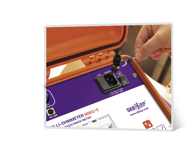
MIKO-9A has the safety certificate IEC 61010-1. The instrument also meets the requirements of electromagnetic compatibility that are applied to class A instruments according to IEC 61326-1.
The instrument has a high degree of protection against:
test cable or mains cable breakdown;
excess of test current;
EMF of self-induction;
overheat of the test block.
At disconnection of the test cable from transformer bushings or from the instrument as well as at disconnection of the mains cable from the mains in the course of measurement, EMF of self-induction of up to several kV is generated in the disconnected circuit and the electric arc appears in the break point.
MIKO-9A is characterized by the redundant protection against EMF of self-induction in case of involuntary disconnection of the test cable or mains cable protecting users from electric shock and the instrument from being damaged.
[~DETAIL_TEXT] =>
MIKO-9A has the safety certificate IEC 61010-1. The instrument also meets the requirements of electromagnetic compatibility that are applied to class A instruments according to IEC 61326-1.
The instrument has a high degree of protection against:
test cable or mains cable breakdown;
excess of test current;
EMF of self-induction;
overheat of the test block.
At disconnection of the test cable from transformer bushings or from the instrument as well as at disconnection of the mains cable from the mains in the course of measurement, EMF of self-induction of up to several kV is generated in the disconnected circuit and the electric arc appears in the break point.
MIKO-9A is characterized by the redundant protection against EMF of self-induction in case of involuntary disconnection of the test cable or mains cable protecting users from electric shock and the instrument from being damaged.
[SORT] => 80
[~SORT] => 80
[DETAIL_TEXT_TYPE] => html
[~DETAIL_TEXT_TYPE] => html
[PROPERTIES] => Array
(
[PREVIEW_ICON] => Array
(
[ID] => 310
[TIMESTAMP_X] => 2019-11-18 14:18:31
[IBLOCK_ID] => 102
[NAME] => Иконка для анонса
[ACTIVE] => Y
[SORT] => 500
[CODE] => PREVIEW_ICON
[DEFAULT_VALUE] =>
[PROPERTY_TYPE] => F
[ROW_COUNT] => 1
[COL_COUNT] => 50
[LIST_TYPE] => L
[MULTIPLE] => N
[XML_ID] => 28
[FILE_TYPE] => jpg, png, jpeg
[MULTIPLE_CNT] => 5
[TMP_ID] =>
[LINK_IBLOCK_ID] => 0
[WITH_DESCRIPTION] => N
[SEARCHABLE] => N
[FILTRABLE] => N
[IS_REQUIRED] => Y
[VERSION] => 1
[USER_TYPE] =>
[USER_TYPE_SETTINGS] =>
[HINT] =>
[PROPERTY_VALUE_ID] => 32699
[VALUE] => 20682
[DESCRIPTION] =>
[VALUE_ENUM] =>
[VALUE_XML_ID] =>
[VALUE_SORT] =>
[~VALUE] => 20682
[~DESCRIPTION] =>
[~NAME] => Иконка для анонса
[~DEFAULT_VALUE] =>
)
[DETAIL_ICON] => Array
(
[ID] => 311
[TIMESTAMP_X] => 2019-11-18 14:18:31
[IBLOCK_ID] => 102
[NAME] => Иконка для описания
[ACTIVE] => Y
[SORT] => 500
[CODE] => DETAIL_ICON
[DEFAULT_VALUE] =>
[PROPERTY_TYPE] => F
[ROW_COUNT] => 1
[COL_COUNT] => 50
[LIST_TYPE] => L
[MULTIPLE] => N
[XML_ID] => 29
[FILE_TYPE] => jpg, png, jpeg
[MULTIPLE_CNT] => 5
[TMP_ID] =>
[LINK_IBLOCK_ID] => 0
[WITH_DESCRIPTION] => N
[SEARCHABLE] => N
[FILTRABLE] => N
[IS_REQUIRED] => Y
[VERSION] => 1
[USER_TYPE] =>
[USER_TYPE_SETTINGS] =>
[HINT] =>
[PROPERTY_VALUE_ID] => 32700
[VALUE] => 20683
[DESCRIPTION] =>
[VALUE_ENUM] =>
[VALUE_XML_ID] =>
[VALUE_SORT] =>
[~VALUE] => 20683
[~DESCRIPTION] =>
[~NAME] => Иконка для описания
[~DEFAULT_VALUE] =>
)
[MORE_PHOTO] => Array
(
[ID] => 312
[TIMESTAMP_X] => 2019-11-18 14:18:31
[IBLOCK_ID] => 102
[NAME] => Фотографии
[ACTIVE] => Y
[SORT] => 500
[CODE] => MORE_PHOTO
[DEFAULT_VALUE] =>
[PROPERTY_TYPE] => F
[ROW_COUNT] => 1
[COL_COUNT] => 50
[LIST_TYPE] => L
[MULTIPLE] => Y
[XML_ID] => 30
[FILE_TYPE] => jpg, png, jpeg
[MULTIPLE_CNT] => 5
[TMP_ID] =>
[LINK_IBLOCK_ID] => 0
[WITH_DESCRIPTION] => Y
[SEARCHABLE] => N
[FILTRABLE] => N
[IS_REQUIRED] => N
[VERSION] => 1
[USER_TYPE] =>
[USER_TYPE_SETTINGS] =>
[HINT] =>
[PROPERTY_VALUE_ID] =>
[VALUE] =>
[DESCRIPTION] =>
[VALUE_ENUM] =>
[VALUE_XML_ID] =>
[VALUE_SORT] =>
[~VALUE] =>
[~DESCRIPTION] =>
[~NAME] => Фотографии
[~DEFAULT_VALUE] =>
)
)
)
Array
(
[ID] => 16545
[~ID] => 16545
[NAME] => Control and data processing software
[~NAME] => Control and data processing software
[IBLOCK_ID] => 102
[~IBLOCK_ID] => 102
[DETAIL_TEXT] =>
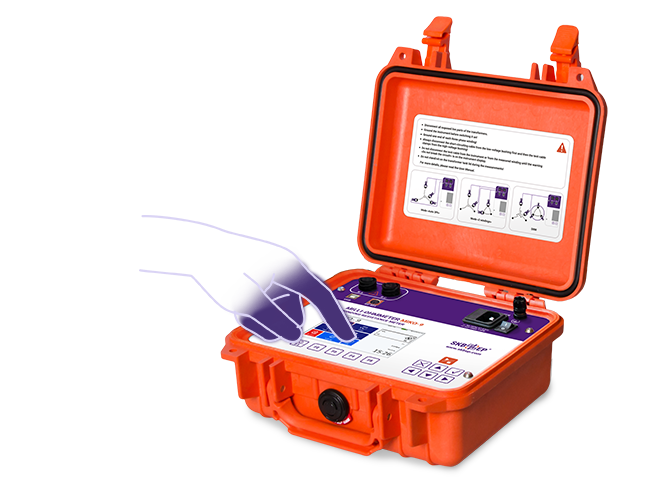
MIKO-9A is equipped with a color graphic touch screen display of high brightness and an intuitive interface, which facilitates interaction with the device. The instrument can be controlled via a keyboard or a touch screen.
The collected data can be:
Synchronized with a mobile app for smartphones/tablets via Bluetooth.
Presented for work and analysis in a cloud web service.
Uploaded to the local version of PC software via USB.
For more information on the types of software products, their differences, and advantages, please see the link → news
[~DETAIL_TEXT] =>
MIKO-9A is equipped with a color graphic touch screen display of high brightness and an intuitive interface, which facilitates interaction with the device. The instrument can be controlled via a keyboard or a touch screen.
The collected data can be:
Synchronized with a mobile app for smartphones/tablets via Bluetooth.
Presented for work and analysis in a cloud web service.
Uploaded to the local version of PC software via USB.
For more information on the types of software products, their differences, and advantages, please see the link → news
[SORT] => 90
[~SORT] => 90
[DETAIL_TEXT_TYPE] => html
[~DETAIL_TEXT_TYPE] => html
[PROPERTIES] => Array
(
[PREVIEW_ICON] => Array
(
[ID] => 310
[TIMESTAMP_X] => 2019-11-18 14:18:31
[IBLOCK_ID] => 102
[NAME] => Иконка для анонса
[ACTIVE] => Y
[SORT] => 500
[CODE] => PREVIEW_ICON
[DEFAULT_VALUE] =>
[PROPERTY_TYPE] => F
[ROW_COUNT] => 1
[COL_COUNT] => 50
[LIST_TYPE] => L
[MULTIPLE] => N
[XML_ID] => 28
[FILE_TYPE] => jpg, png, jpeg
[MULTIPLE_CNT] => 5
[TMP_ID] =>
[LINK_IBLOCK_ID] => 0
[WITH_DESCRIPTION] => N
[SEARCHABLE] => N
[FILTRABLE] => N
[IS_REQUIRED] => Y
[VERSION] => 1
[USER_TYPE] =>
[USER_TYPE_SETTINGS] =>
[HINT] =>
[PROPERTY_VALUE_ID] => 32701
[VALUE] => 20685
[DESCRIPTION] =>
[VALUE_ENUM] =>
[VALUE_XML_ID] =>
[VALUE_SORT] =>
[~VALUE] => 20685
[~DESCRIPTION] =>
[~NAME] => Иконка для анонса
[~DEFAULT_VALUE] =>
)
[DETAIL_ICON] => Array
(
[ID] => 311
[TIMESTAMP_X] => 2019-11-18 14:18:31
[IBLOCK_ID] => 102
[NAME] => Иконка для описания
[ACTIVE] => Y
[SORT] => 500
[CODE] => DETAIL_ICON
[DEFAULT_VALUE] =>
[PROPERTY_TYPE] => F
[ROW_COUNT] => 1
[COL_COUNT] => 50
[LIST_TYPE] => L
[MULTIPLE] => N
[XML_ID] => 29
[FILE_TYPE] => jpg, png, jpeg
[MULTIPLE_CNT] => 5
[TMP_ID] =>
[LINK_IBLOCK_ID] => 0
[WITH_DESCRIPTION] => N
[SEARCHABLE] => N
[FILTRABLE] => N
[IS_REQUIRED] => Y
[VERSION] => 1
[USER_TYPE] =>
[USER_TYPE_SETTINGS] =>
[HINT] =>
[PROPERTY_VALUE_ID] => 32702
[VALUE] => 20686
[DESCRIPTION] =>
[VALUE_ENUM] =>
[VALUE_XML_ID] =>
[VALUE_SORT] =>
[~VALUE] => 20686
[~DESCRIPTION] =>
[~NAME] => Иконка для описания
[~DEFAULT_VALUE] =>
)
[MORE_PHOTO] => Array
(
[ID] => 312
[TIMESTAMP_X] => 2019-11-18 14:18:31
[IBLOCK_ID] => 102
[NAME] => Фотографии
[ACTIVE] => Y
[SORT] => 500
[CODE] => MORE_PHOTO
[DEFAULT_VALUE] =>
[PROPERTY_TYPE] => F
[ROW_COUNT] => 1
[COL_COUNT] => 50
[LIST_TYPE] => L
[MULTIPLE] => Y
[XML_ID] => 30
[FILE_TYPE] => jpg, png, jpeg
[MULTIPLE_CNT] => 5
[TMP_ID] =>
[LINK_IBLOCK_ID] => 0
[WITH_DESCRIPTION] => Y
[SEARCHABLE] => N
[FILTRABLE] => N
[IS_REQUIRED] => N
[VERSION] => 1
[USER_TYPE] =>
[USER_TYPE_SETTINGS] =>
[HINT] =>
[PROPERTY_VALUE_ID] =>
[VALUE] =>
[DESCRIPTION] =>
[VALUE_ENUM] =>
[VALUE_XML_ID] =>
[VALUE_SORT] =>
[~VALUE] =>
[~DESCRIPTION] =>
[~NAME] => Фотографии
[~DEFAULT_VALUE] =>
)
)
)
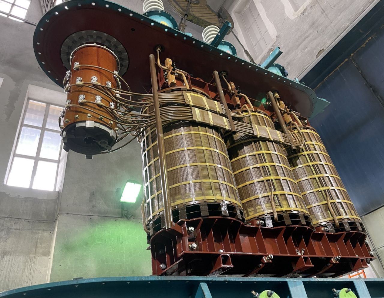
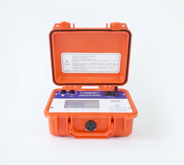
MIKO-9A milli-ohmmeter is developed to measure DC resistance in the range of 1 µΩ - 30 kΩ with test current up to 10 А, as well as to generate oscillograms of a switching contactor in the high-speed OLTC; it also provides for demagnetization and "Heat Run Test".
MIKO-9A diagnostic objects:
Windings of power and instrument transformers, windings of electric motors, generators, linear compensators and windings of other high-inductive equipment;
High-speed OLTCs;
Contacts of circuit breakers, resistors, buses and other non-inductive circuit;
Compensatory, current limiting and other resistors of high-voltage circuit breakers;
Сables.
Resistance measurement and test current ranges are automatically selected, it is possible to adjust the test current manually. The instrument ensures fully automated resistance measurement of highly inductive load and thermal EMF balancing in external circuit.
MIKO-9A implements specialized measurement modes for various configurations of 11 objects (resistive object, inductive object, voltage transformer, current transformer and power transformer, generator, motor, reactor, compensator, connection filter and magnet), taking into account their specific features. The user can select a standard object from the list, or create his own object.
The device automatically takes into account the configuration of the object for setting measurement modes.
Watch detailed video-reviews about MIKO-9A milli-ohmmeter up above ↑ or on the video page.
Depending on the object type, special measurement modes can be selected. For a resistive object, the modes are completely similar to the MIKO-8М(А), and for an inductive object, in addition to the two modes MANUAL and AUTO 1Ph, you can select AUTO 3Ph and 2 WINDINGS.
AUTO 3Ph makes it possible to simultaneously connect to three phases of the transformer and take measurements with automatic switching between them. This mode reduces the amount of reconnecting to/from the object under test.
AUTO 1Ph and AUTO 3Ph modes have SKB EP patented automatic measurement method that guarantees results with the highest accuracy in challenging electromagnetic environments.
During the measurement process, the device calculates the estimated resistance of the object, excluding the need to select a measurement subrange, and sets the max power measurement current for the measured circuit. This ensures measurement accuracy in substation interference conditions approaches laboratory conditions.
A special measurement signal delivery mode also reduces the current and voltage stabilization time, reducing the overall measurement time.
Depending on the object type, special measurement modes can be selected. For a resistive object, the modes are completely similar to the MIKO-8М(А) device, and for an inductive object, in addition to the three modes MANUAL, AUTO 1Ph and AUTO 3Ph, you can choose 2 WINDINGS mode.
This mode enables resistance measurement simultaneously on two windings, and guarantees a quick and reliable measurement of the electrical resistance of heavy power transformers, in particular, with secondary windings delta connected when using traditional methods does not give a stable result.
The device indicates which phases should be connected to accelerate the measurement process, taking into account the distribution of magnetic fluxes in the magnetic circuit. In addition, the simultaneous measurement of two windings reduces the total number of test cable reconnection from 6 to 3.
Demagnetization mode is designed to eliminate the remnant magnetism of the transformer magnetic core. It is compulsory to be made before open-circuit test, short-circuit loss measurement, transformation ratio measurement, etc.
The instrument can be used for demagnetization of both single-phase and three-phase transformers. Magnetic core demagnetization requires alternating current applied to the corresponding winding bidirectionally.
Demagnetization is performed automatically. Current decreases with each direction change. Each rod of a three-phase transformer is subjected to demagnetization.
Current change is at the same time displayed in a graph form to control demagnetization accuracy. Demagnetization stops automatically when the current reaches threshold value or upon the user’s command
OLTC non-demountable check mode allows the user to assess the state of the switching OLTC equipment with current limiting resistors without removing the contactor tank cover.
This mode involves measuring of instant test current values. Test current firstly passes through the transformer winding and then through OLTC contacts at switching from one tap to another. The DRM graph is built on the basis of the measurement results and shows current change during tap changing. This graph enables to check tap changing time and general object state.
Analysis of the acquired graphs enables not only to sort out OLTC by fault-free/faulty criteria but also to define the nature of the defect eliminating the opening of fault-free OLTCs. Milli-ohmmeter mode and DRM test complement each other and provide the user comprehensive information about the transformer state.
The test is performed by continuous measurement and periodic result saving of the transformer winding resistance (recalculated to t°) during the cooling process of the winding.
To receive the most reliable information about the max winding t° the user should connect the instrument to the winding and start the measurement immediately after the transformer heating is stopped.
Before the start of the measurement process the user has to specify winding, phase, max measurement duration, frequency of measurement results saving, winding resistance and temperature under normal conditions. Correlation between the winding temperature and the time can be represented in tabular or graphical form. The time is counted from the moment of the measurement start. Heat run test stops automatically on expiry of preset test duration or manually by the user.
MIKO-9A has a built-in archive of up to 1,000 measurements for viewing, copying or deleting data. And due to the possibility of choosing an object at the measurement stage, the results are presented more systematically. This facilitates interaction with the archive.
The group of MIKO-7M(A), MIKO-8M(A) and MIKO-9A instruments has a number of automatic recalculation functions:
Auto δ calculation of Rphasebetween one another.
Auto conversion of Rlinear to Rphase. Linear windings are Delta or Star without neutral connected.
Auto correction of R measured at t° to R at t°p taking into account the winding material.
Auto δ calculation between Rcorrected and Rp.
Auto calculation of t° by its R.
Measurement results are automatically saved to the non-volatile memory and can be later processed by special software on PC or transmitted via Bluetooth to a smartphone.
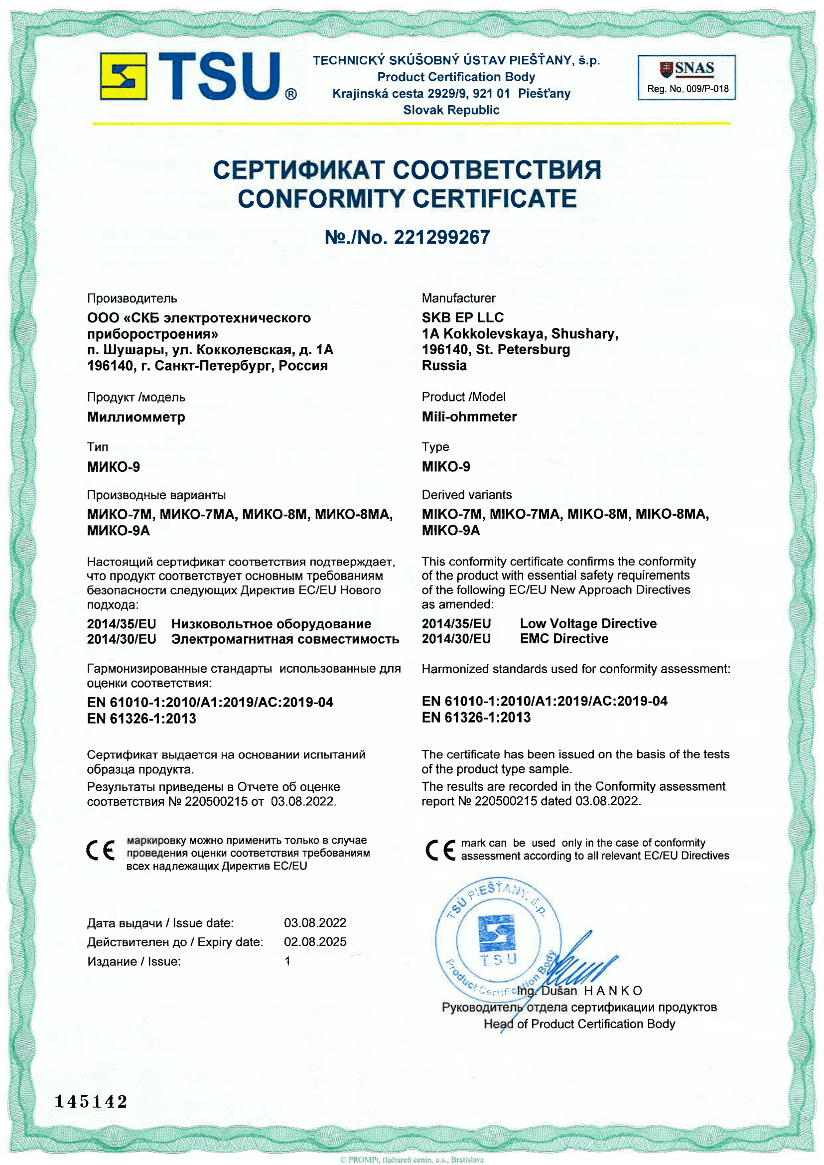
MIKO-9A has the safety certificate IEC 61010-1. The instrument also meets the requirements of electromagnetic compatibility that are applied to class A instruments according to IEC 61326-1.
The instrument has a high degree of protection against:
test cable or mains cable breakdown;
excess of test current;
EMF of self-induction;
overheat of the test block.
At disconnection of the test cable from transformer bushings or from the instrument as well as at disconnection of the mains cable from the mains in the course of measurement, EMF of self-induction of up to several kV is generated in the disconnected circuit and the electric arc appears in the break point.
MIKO-9A is characterized by the redundant protection against EMF of self-induction in case of involuntary disconnection of the test cable or mains cable protecting users from electric shock and the instrument from being damaged.
MIKO-9A is equipped with a color graphic touch screen display of high brightness and an intuitive interface, which facilitates interaction with the device. The instrument can be controlled via a keyboard or a touch screen.
The collected data can be:
Synchronized with a mobile app for smartphones/tablets via Bluetooth.
Presented for work and analysis in a cloud web service.
Uploaded to the local version of PC software via USB.
For more information on the types of software products, their differences, and advantages, please see the link → news
Specifications
Value
Resistance range
1 μΩ - 30 kΩ
Resolution capability
0.1 μΩ
Accuracy
±(0.1%+0.5 µΩ)
Test current output
0.0005 A - 10 A
Test current range in DRM mode
0.1 A - 10 A
Measurement display resolution
5 digits
MIKO-9A: Power supply (built-in battery)
Li-ion battery
MIKO-9A: Battery charge time
3 hours
MIKO-9A: Duration of continuous operation of the battery
8 hours
Built-in memory
up to 1,000 measurements
PC connection
USB, RS-485 and Bluetooth (optional)
Display
Color graphic TFT touch, 800 x 480 pixels
Power consumption
120 W
Output capacity, W
60 W
MIKO-9A: Power supply (mains voltage)
90-253 V AC, 47-63 Hz 127-354 V DC
Dimensions
270 х 250 х 130 mm
MIKO-9A: Main instrument weight
4.0 kg
Operating temperature range
-20ºС - +55ºС
Environmental protection with open cover
IP40
Environmental protection with closed cover
IP67
Interface and user manual language
English
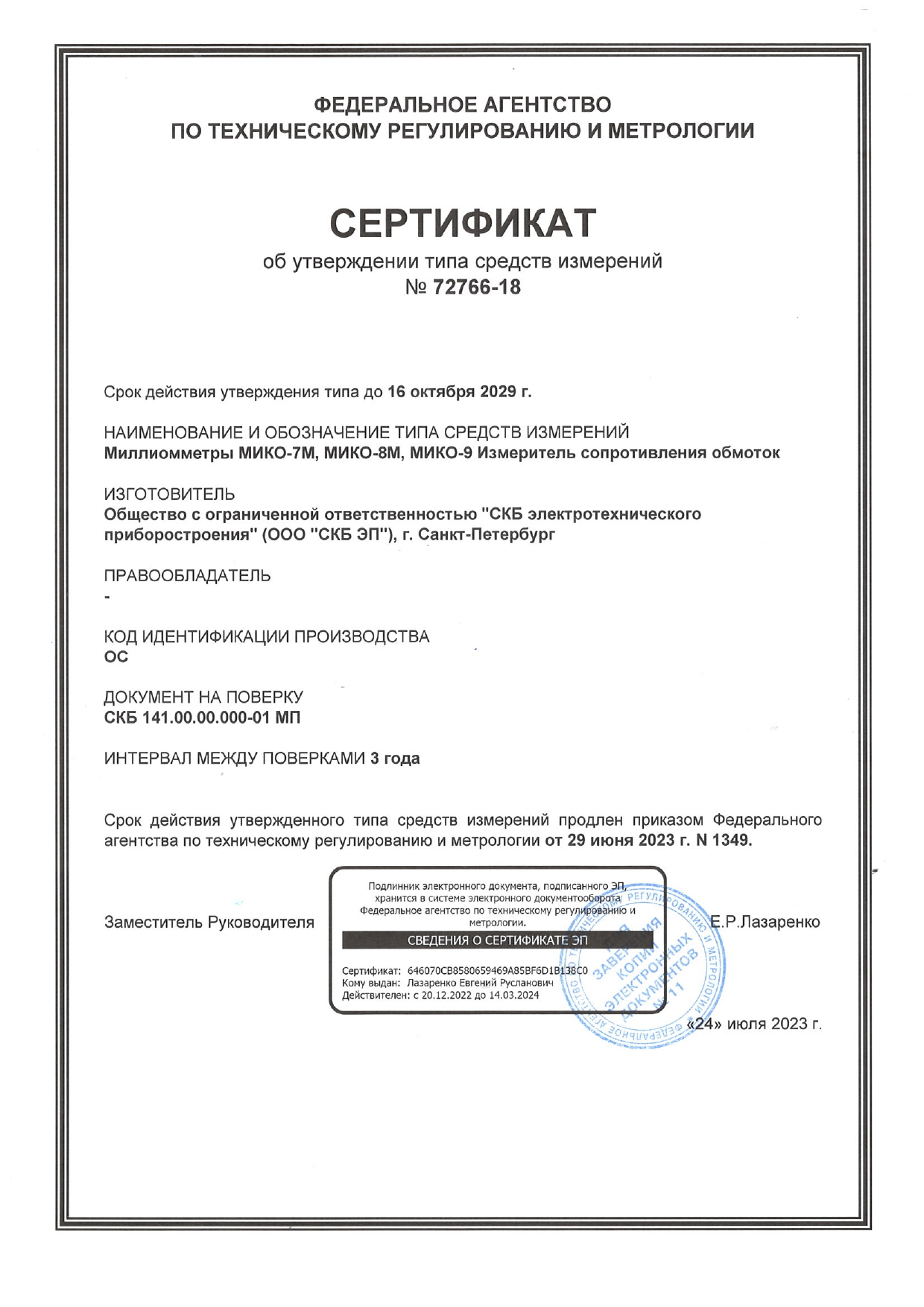
Testing period
3 years
Calibration period
3 years
Warranty period
3 years
Standard complete set
Photo
Item, Index
Application
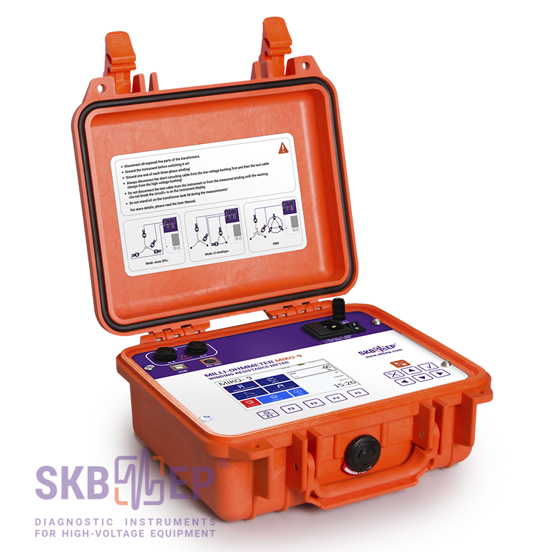
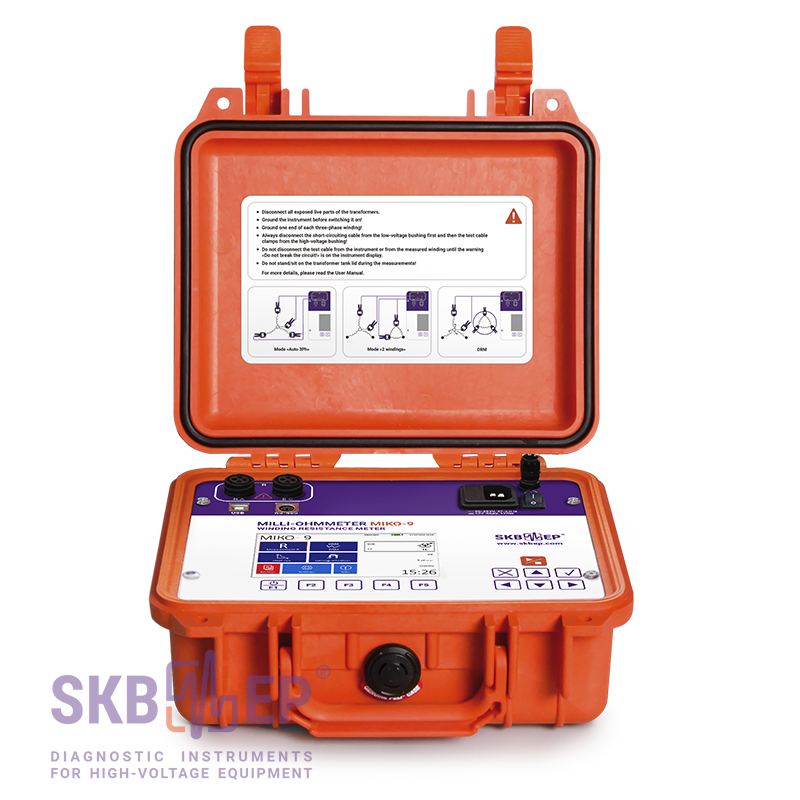
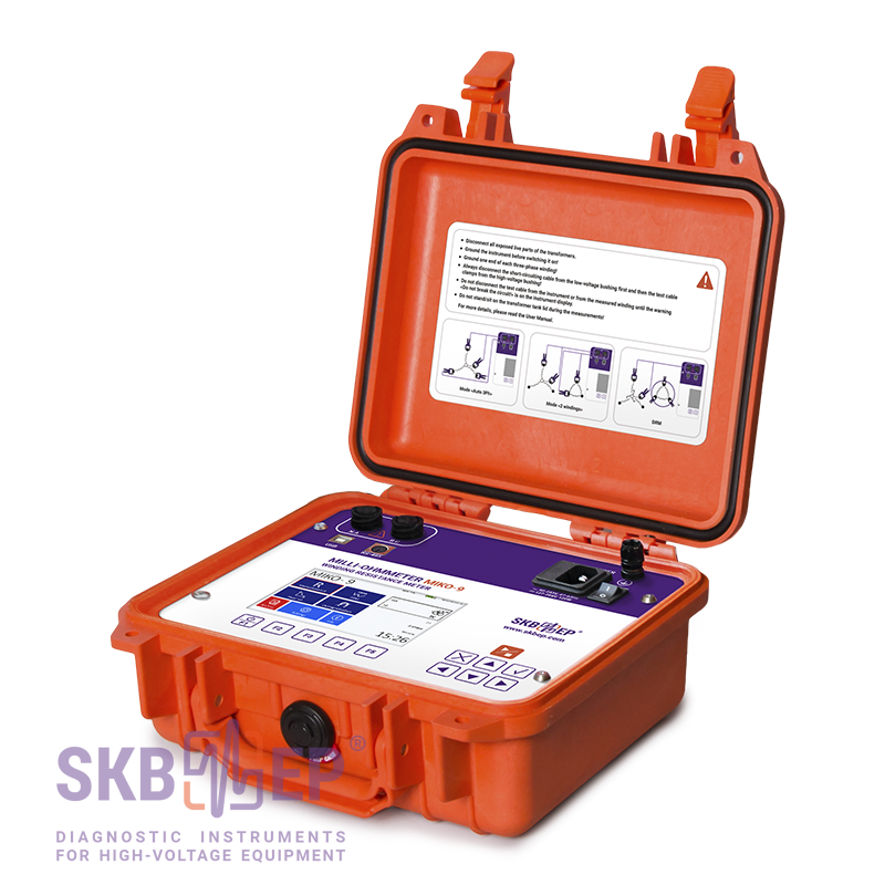
MIKO-9A main instrument
041.00.000-01
MIKO-9A main instrument
041.00.000-01
Instrument and documents: User Manual, and a Log Book.
Test cables on order
Test cables on order
As a matter of convenience for the user, test cables are not included to the standard complete set. Each user can select a cable to his/her own requirements.
Please, select at least one test cable (see "additional complete set on order" below).
Mains cable
018.09.00.000
Mains cable
018.09.00.000
Mains cable 1 x 2 m. Weight 0.24 kg. For instrument connection to the main network. Temperature range -25°С - +120°С. Rubber insulation.
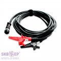
Ground cable
010.01.00.000
Ground cable
010.01.00.000
Ground cable 1 x 2 m. Weight 0.08 kg. For instrument grounding. The cable is equipped with a ground clamp and a screw end cap. Nominal test current is 50 A.
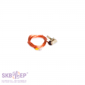
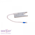
Zero resistance standard
023.15.00.000
Zero resistance standard
023.15.00.000
Resistance zero point accuracy check. Value – 0.000 µOhm.
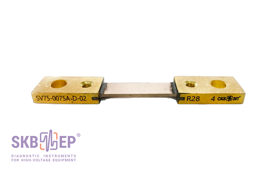
Shunt
Shunt
Type: SV75-0075A-D-02. For checking MIKO-9A operability. Value – 1 mΩ ± 0.5%. SKB EP part.
Fuses
Fuses
Type: VP2B-1V-2A (ВП2Б-1В-2А) (2 pcs). For the power source protection.
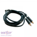
USB 2.0 A-B Cable
USB 2.0 A-B Cable
USB cable 1 x 1.8 m. For computer connection and data transfer.
Attachment devices set kit
126.06.02.000
Attachment devices set kit
126.06.02.000
Additional complete set (on order)
Photo
Item, Index
Application
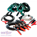
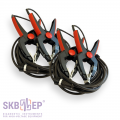
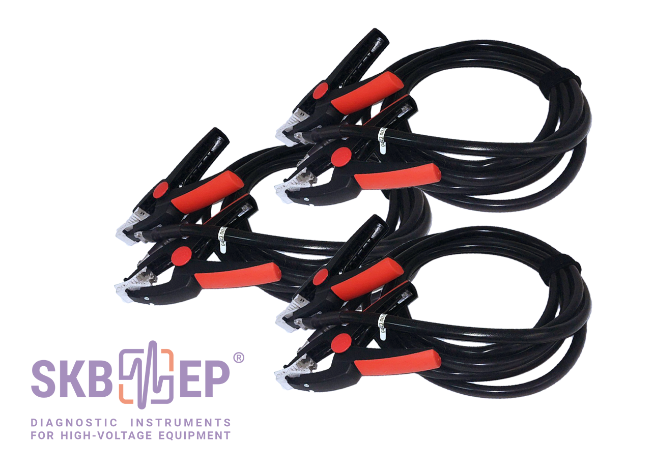
Test cable (set of 2 pcs.)
041.22.00.000<br>041.22.00.000-01
Test cable (set of 2 pcs.)
041.22.00.000<br>041.22.00.000-01
10A Kelvin Clamp test cable 2 x 8.5 m (grip up to 70 mm) for connection to transformer bushings. Modification of the 041.18.00.000(-01) cable. To be used on transformers with bushings located close to each other. Set weight 3.45 kg (1.72 kg + 1.72 kg).
Elastic silicone tube resistant to low and high temperatures, and corrosive media.
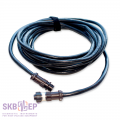
Test cable (set of 2 pcs.)
041.30.00.000<br>041.30.00.000-01
Test cable (set of 2 pcs.)
041.30.00.000<br>041.30.00.000-01
10A Kelvin Clamp test cable 2 x 3.5 m (jaw up to 50 mm) for connection to transformer bushings. To be used on transformers with bushings located close to each other. Set weight 1.52 kg (0.76 kg + 0.76 kg).
Elastic silicone tube resistant to low and high temperatures, and corrosive media.
Test cable
041.19.00.000
Test cable
041.19.00.000
10A Kelvin test cable 1 x 3 m. Weight 0.5 kg.
With 2 probes and 4 crocodile clips (jaw up to 25 mm) (length: 30 mm, plug: 3 mm) for contact resistance measurement of CT and VT contact joints and windings.
Test cable (set of 2 pcs.)
041.26.00.000<br>041.26.00.000-01
Test cable (set of 2 pcs.)
041.26.00.000<br>041.26.00.000-01
10A Kelvin C-clamp test cable 2 x 8.5 m (jaw up to 103 mm) for connection to transformer bushings. Set weight 4.42 kg (2.2 kg + 2.22 kg).
Alternative version of test cables 041.22.00.000(-01).
Test cable (set of 2 pcs.)
041.29.00.000<br>41.29.00.000-01
Test cable (set of 2 pcs.)
041.29.00.000<br>41.29.00.000-01
10A Kelvin Clamp test cable 2 x 3.5 m (grip up to 70 mm) for connection to transformer bushings. Set weight 1.87 kg (0.92 kg + 0.95 kg).
Elastic silicone tube resistant to low and high temperatures and corrosive media.
Test cables for CT and VT
041.21.00.000
Test cables for CT and VT
041.21.00.000
10A Kelvin Clamp test cable 1 x 4 m (jaw up to 20 mm) for resistance measurement of CT and VT windings. Weight 0.61 kg.
Cable is used for CTs and VTs which are stand-alone or built into transformers / circuit breakers.
Test cable
041.28.00.000
Test cable
041.28.00.000
10A Kelvin test cable 1 x 3 m, 0,54 kg, with spring-loaded probes. To be used for electrical resistance measurement in hard-to-reach place.
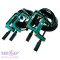
Test cable extension (set of 2 pcs.)
031.20.00.000
Test cable extension (set of 2 pcs.)
031.20.00.000
Extension cable 2 x 6.5 m. Set weight 2.33 kg (1.17 kg + 1.16 kg).
Elastic silicone tube resistant to low and high temperatures and corrosive media. To be used together with test cables 041.18.00.000/(-01), 041.22.00.000/(-01), 041.26.00.000/(-01), 041.29.00.000 and 041.30.00.000/(-01).
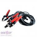
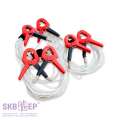
Short-circuiting cable (set of 3 pcs.)
041.23.00.000
Short-circuiting cable (set of 3 pcs.)
041.23.00.000
Short-circuiting cable set 3 x 3 m with crocodile clips (jaw up to 70 mm). Set weight 1.89 kg (0.63 kg + 0.63 kg + 0.63 kg).
The set is used for applying the DRM-test by short-circuiting secondary circuits. <b>This cable is for OLTCs of power transformers, application on transformers up to and including 40,000 kVA capacity.
Furthermore, this cable is needed for connecting high-voltage and low-voltage windings when 2 windings mode is applied.
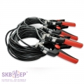
Short-circuiting cable (set of 3 pcs.)
035.31.00.000
Short-circuiting cable (set of 3 pcs.)
035.31.00.000
Short-circuiting cable set 3 x 12 m with crocodile clips (jaw up to 50 mm). Set weight 0.8 kg (0.27 kg + 0.27 kg + 0.27 kg).
The set is used for applying the DRM test by short-circuiting secondary circuits. <b>This cable is for OLTCs of power and auto transformers.
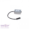
Additional resistor
032.25.00.000
Additional resistor
032.25.00.000
For non-demountable OLTC monitoring at total resistance of the winding of no more than 0.5 Ω. Length 0.11 m + 0.35 m. Weight 0.23 kg.
KMDLAX-6P plug
KMDLAX-6P plug
An adapter for the RS-485 cable for the analyzer communication with the SCADA-controlled measurement system.
Adapter for a reference coil
023.12.00.000
Adapter for a reference coil
023.12.00.000
For testing laboratories: inspection / calibration of the instrument. Length 0.025 m + 0.16 m. Weight 0.04 kg.
Tool bag
126.06.00.000
Tool bag
126.06.00.000
Convenient, robust, wear proof bag for transportation of cables, documentation and other accessories to the MIKO-9A instrument.
Weight 0.6 kg.
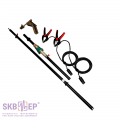
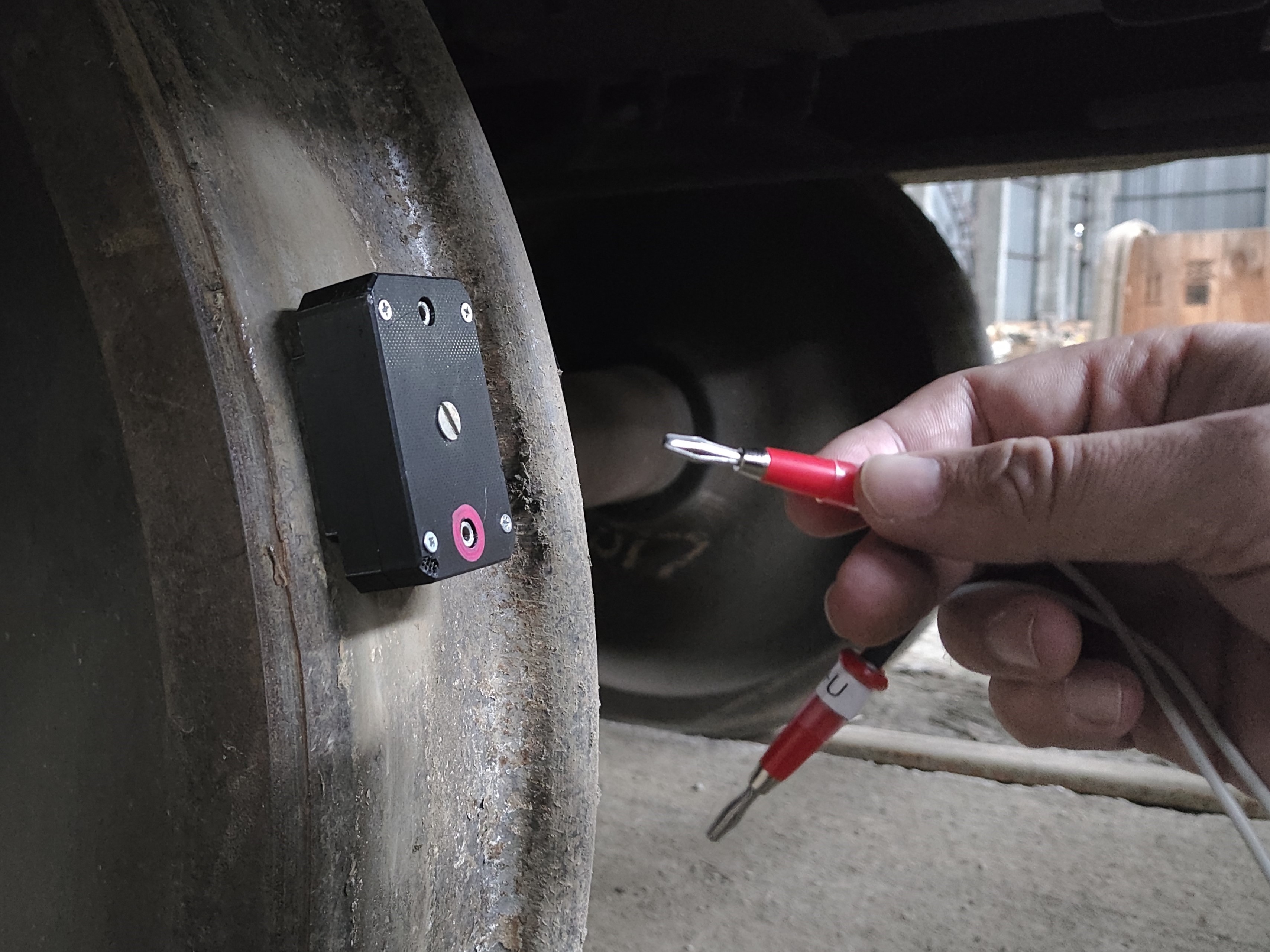
Manipulating rod
010.41.00.000 010.41.00.000-01 010.41.00.000-02
Manipulating rod
010.41.00.000 010.41.00.000-01 010.41.00.000-02
Manipulating rod is designed for test cables connection from the ground or from the tank cover to the bushings of high-voltage circuit breakers, and to the structural elements of high-voltage disconnecting switches and earthing devices, without the use of ladders or elevated platforms.
The manipulating rod is completed with special extension cables. There is a Kelvin clamp with current and potential contacts to connect to the object on one side, and a contact pad on the other side. The device test cable is connected to the contact pad from the ground or a tank cover.
Manipulating rod extension cable is made according to a four-wire (Kelvin) scheme with the test current capacity of 100 A in the presence of a good contact.
Manipulating rod</a> - 2.2 (length 2.2 m / weight as an assembled set 3.4 kg);
Manipulating rod</a> - 3.7 (length 3.7 m / weight as an assembled set 4.0 kg);
Manipulating rod</a> - 5.1 (length 5.1 m / weight as an assembled set 4.6 kg).
Official reviews from customers based on the results of operating SKB EP instruments are available upon request. Please, fill out the form on the website.
 Русский
 Français
 Chinese