Saving the TMN-6300/35-U1 transformer - a successful MIKO-9A case
A power transformer TMN-6300/35-U1 was delivered to the laboratory of JSC IESK for diagnostics and repair after a long downtime. Initially, the laboratory specialists conducted measurements using a device from another manufacturer "Analog N" (conditional name), where significant deviations in ohmic resistance between phases (40%) and rejection in open-circuit tests were recorded.
The task was to restore the object, but during the first tests, there were indications of its complete malfunction and writing it off as "scrap metal".
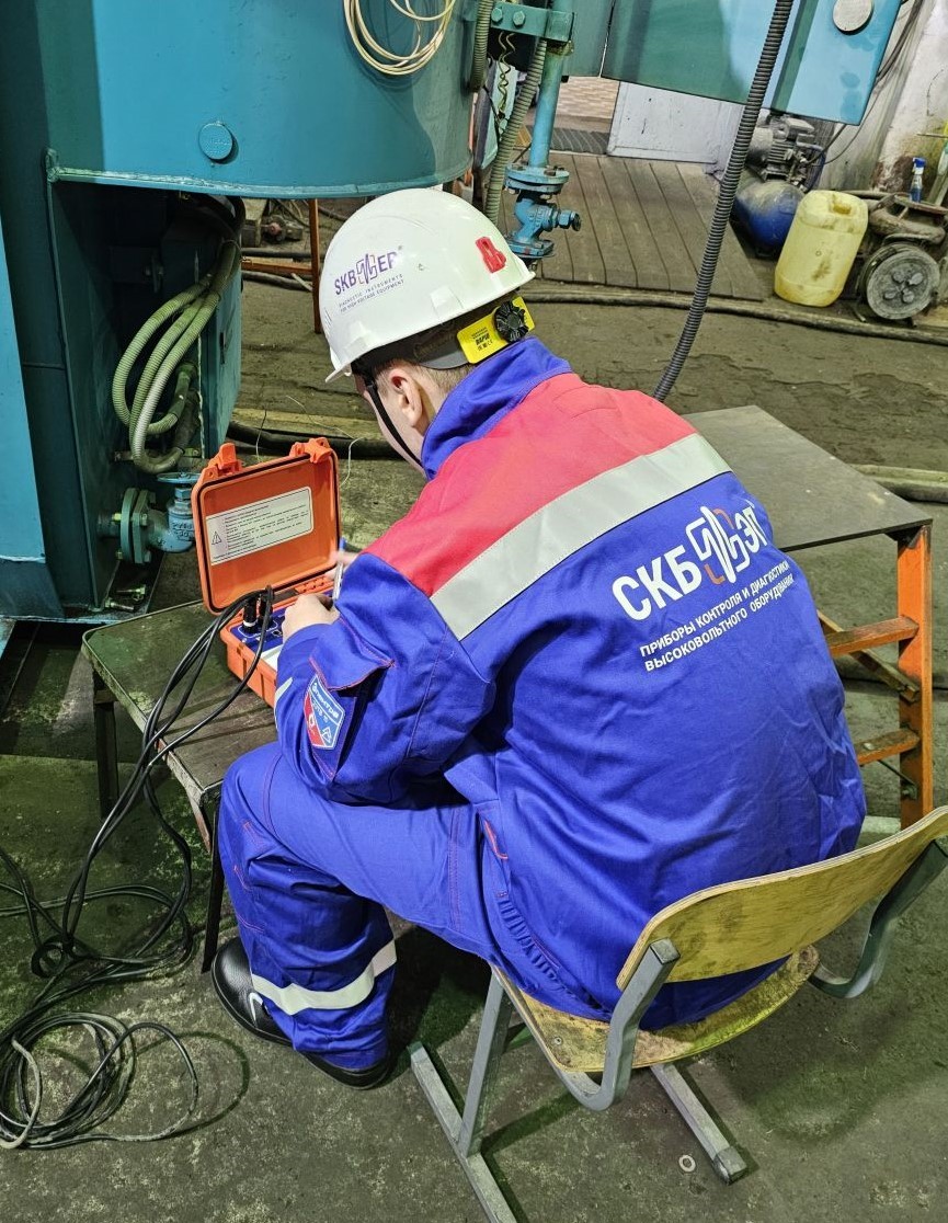
Specialists of JSC IESK applied to SKB EP LLC with a request to assist in the diagnosis of TMN-6300/35-U1 with the search for possible malfunctions using MIKO-9A milli-ohmmeter, as well as the need to specify the capabilities of MIKO-9A in comparison with the existing instrument.
The four-channel milli-ohmmeter MIKO-9A is designed to measure resistance in inductive and non-inductive circuits in the range of 1 μΩ - 30 kΩ at a current of up to 10A. The instrument has high accuracy corresponding to class 0.1, which is maintained not only in laboratory conditions but also at substations under industrial interference conditions. This is achieved due to the fact that for any winding resistance, its own maximum possible test current is calculated and set, limited only by the useful power of the instrument. Therefore, the ratio of the useful signal on the winding to the amplitude of the interference remains high at any resistance (Patent for Method for measuring DC resistance of windings of electrical equipment).
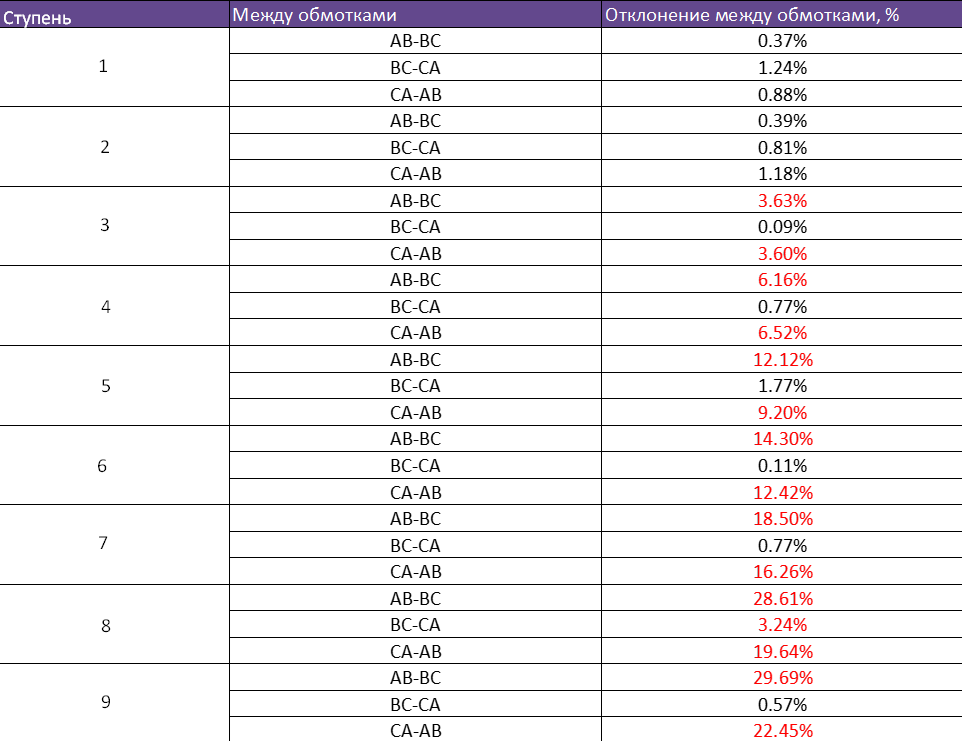
When measuring the resistance of the windings of TMN-6300/35-U1 with MIKO-9A, deviation in the ohmic resistance was confirmed.
- Measurements were taken in all phases and in all positions of OLTC. However, MIKO-9A recorded and automatically calculated (auto recalculation function) a resistance deviation on phases AB, BC, and CA of 28%, whereas "Analog N" showed values that, when manually recalculated, amounted to 40%.
- Since the deviation was confirmed and did not depend on the measuring instrument, a mutual decision was made to disassemble the transformer and remove the active part to find the cause of the malfunction.
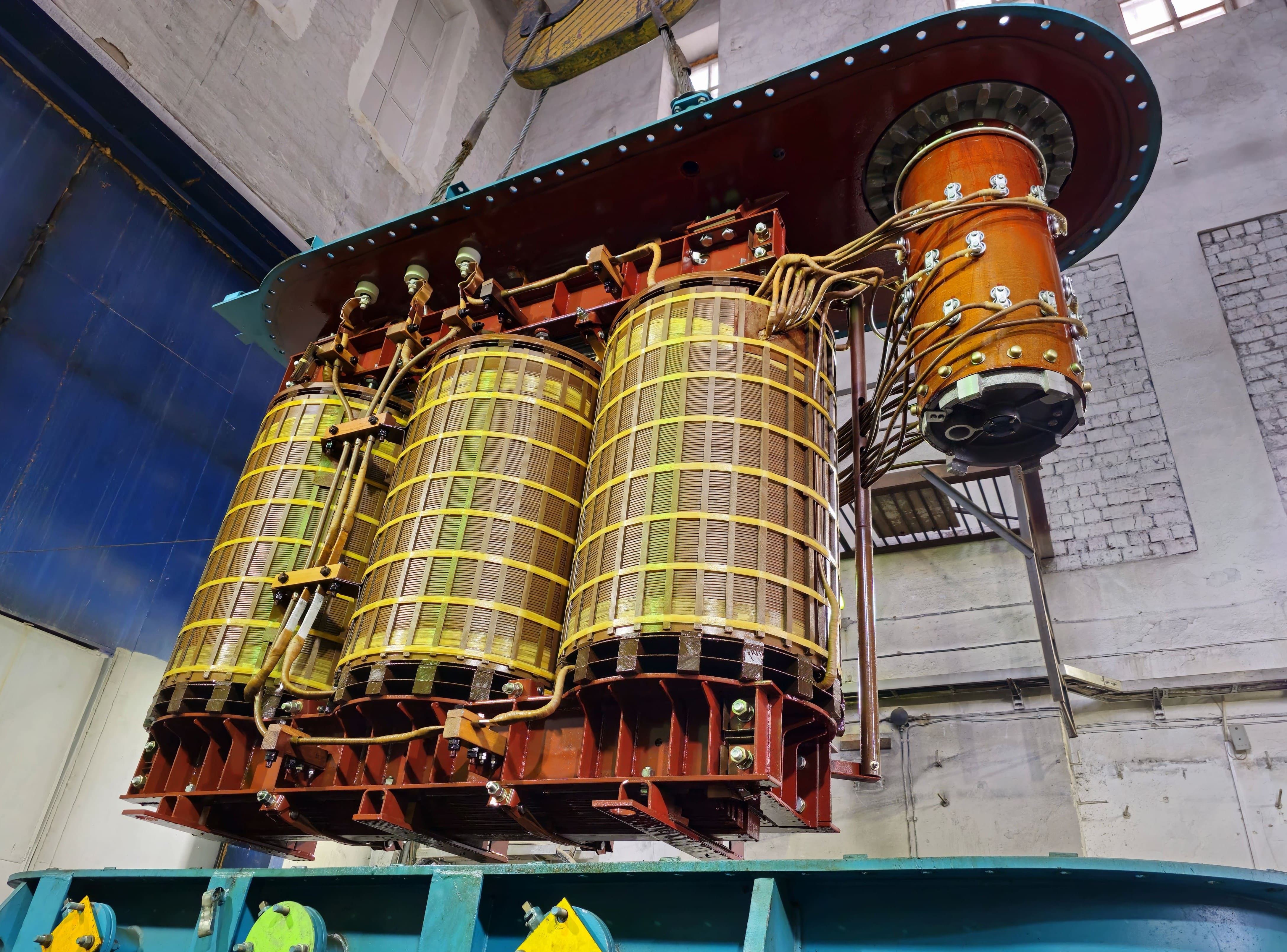
- After removing the active part of the transformer, no visual damage or deviations were found, no heating spots were detected, and no loose elements were identified. It was decided to measure the ohmic resistance of the windings without taking into account the "influence" of OLTC, in order to determine the integrity of the windings.
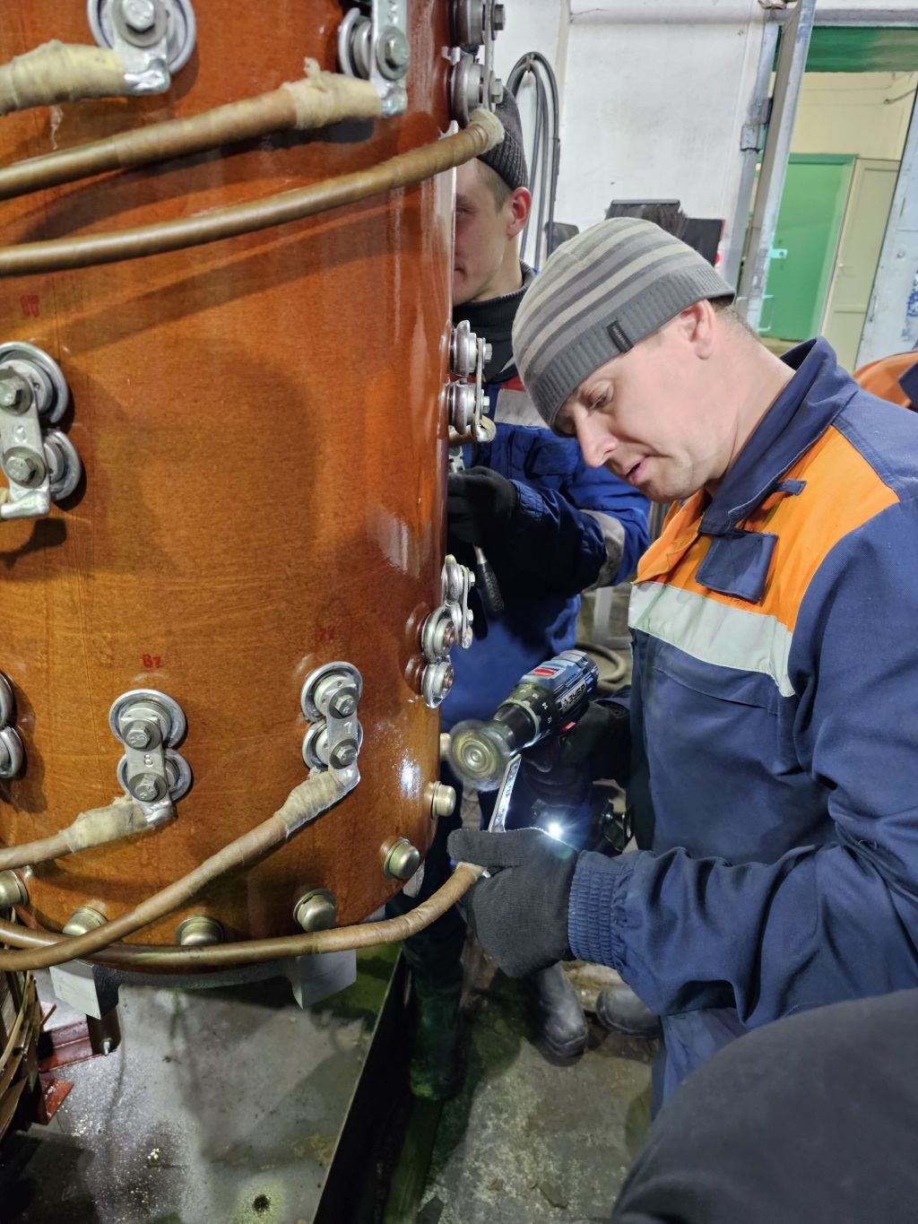
- The most common cause of malfunctions is oxidation of contacts, and since the condition of the windings is normal, it was determined that it is necessary to clean the connection points of the regulating winding to the OLTC.
- "Automatic three-phase" resistance measurement mode , which consists in sequential automatic measurement in three phases with automatic stop and result indication;
- "Two-winding" mode for fast and reliable measurement of the resistance of high-power power transformers, particularly, with the secondary windings connected in a delta configuration, when traditional methods do not provide stable results;
- the presence of a "base" of built-in measurement objects (power transformer, current transformer, voltage transformer, resistive object, generator, etc.) to account for specific features before measurement and to systematize data in the archive;
- "DRM test" mode for express checking of the technical condition of the OLTC contactor without opening it, by connecting to the transformer bushings.
- "Heat Run Test " mode or cooling test. The order of tests and the rules for processing the results comply with the requirements of clause 2. GOST 3484.2-88 "Power transformers. Heating tests"
- "Demagnetization" mode, which is implemented in accordance with GOST 3484.1-88. The user can operate in fully automatic mode as well as in manual mode with a test current step change of up to 1% (while the total demagnetization time increases accordingly).
-
increase the efficiency of power transformer inspections;
-
thanks to multichannel capability, increase the accuracy of measuring the electrical resistance of three-phase transformer windings;
- get additional information about the technical condition of the OLTC contactor.
While working with "Analog N", there was a significant variation in measurement results, and there was no stability in the readings. This may be due to the low test current of 100 mA and the specific approach to recording results by the specialists themselves, who waited for instrument readings to stabilize for a short time. Most likely, it was the low test current and the difficulties in recording the results that caused the overestimation in the percentage deviation of resistances between phases. The MIKO-9A milli-ohmmeter on TMN-6300/35-U1 transformer had a test current of 3 - 4 A depending on the tap.
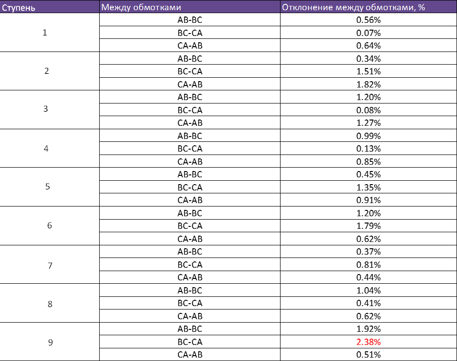
Results of measuring the ohmic resistance with MIKO-9A milli-ohmmeter at the beginning of work with TMN-6300/35-U1 transformer
Measurement of windings without OLTC showed normal values, which was confirmed by using MIKO-9A milli-ohmmeter, whose deviation indicators did not exceed 2%. In parallel, "Analog N" was engaged, which recorded a deviation of more than 2%. As a reference point for making a decision, we determined MIKO-9A and proceeded to further search for the cause.
This solution gave positive results, the resistance decreased at the position of the OLTC, where the contacts were cleaned. After cleaning all the contacts, the ohmic resistance returned to normal, both in the disassembled state and after bringing the object into working condition.
Competent diagnostics using the MIKO-9A milli-ohmmeter
saved the transformer from being written off as "scrap metal"!
Results of measuring the ohmic resistance with MIKO-9A milli-ohmmeter after malfunction detection and elimination
In addition to the accuracy and automation of the recalculation and deviation process, the MIKO-9A has additional functionality that makes the instrument a true measuring complex:
Compared to single-channel ohmmeters, micro-ohmmeters, and milli-ohmmeters, the four-channel MIKO-9A allows to:

 Русский
 Français
 Chinese
