Array
(
[ID] => 16510
[~ID] => 16510
[NAME] => Wide functionality and high accuracy ±0.05%
[~NAME] => Wide functionality and high accuracy ±0.05%
[IBLOCK_ID] => 102
[~IBLOCK_ID] => 102
[DETAIL_TEXT] =>
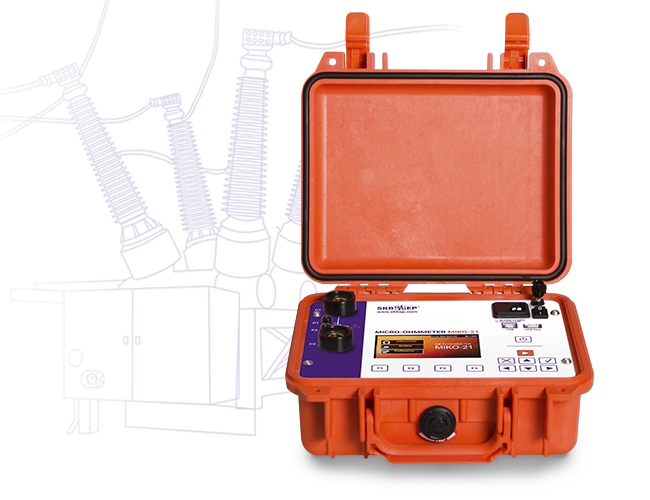
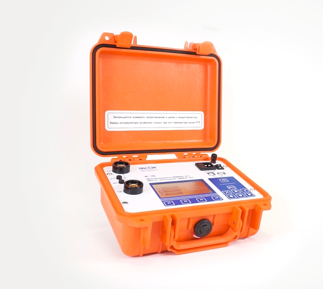
MIKO-21 is designed for high precision measurements of DC electrical resistance in the range from 0.1 µΩ to 2 Ω with an accuracy of ±0.05% and can test:
contacts of high-voltage circuit breakers of all types and voltage classes;
contactors, relays, busbars, various bolted connections, welded joints, brazed joints;
elements of equipment for open and closed switchgears in extreme electric and magnetic field conditions;
in research laboratories and industrial workshops.
MIKO-21 is ahead of similar devices represented on the market due to a number of functional and technical features. For example, special measuring technologies ensure MIKO-21 compliance with the most stringent accuracy requirements. MIKO-21 is ideally applicable for high precision resistance tests in the µΩ range.
Watch detailed video-reviews about MIKO-21 micro-ohmmeter up above ↑ or on the video page
[~DETAIL_TEXT] =>
MIKO-21 is designed for high precision measurements of DC electrical resistance in the range from 0.1 µΩ to 2 Ω with an accuracy of ±0.05% and can test:
contacts of high-voltage circuit breakers of all types and voltage classes;
contactors, relays, busbars, various bolted connections, welded joints, brazed joints;
elements of equipment for open and closed switchgears in extreme electric and magnetic field conditions;
in research laboratories and industrial workshops.
MIKO-21 is ahead of similar devices represented on the market due to a number of functional and technical features. For example, special measuring technologies ensure MIKO-21 compliance with the most stringent accuracy requirements. MIKO-21 is ideally applicable for high precision resistance tests in the µΩ range.
Watch detailed video-reviews about MIKO-21 micro-ohmmeter up above ↑ or on the video page
[SORT] => 10
[~SORT] => 10
[DETAIL_TEXT_TYPE] => html
[~DETAIL_TEXT_TYPE] => html
[PROPERTIES] => Array
(
[PREVIEW_ICON] => Array
(
[ID] => 310
[TIMESTAMP_X] => 2019-11-18 14:18:31
[IBLOCK_ID] => 102
[NAME] => Иконка для анонса
[ACTIVE] => Y
[SORT] => 500
[CODE] => PREVIEW_ICON
[DEFAULT_VALUE] =>
[PROPERTY_TYPE] => F
[ROW_COUNT] => 1
[COL_COUNT] => 50
[LIST_TYPE] => L
[MULTIPLE] => N
[XML_ID] => 28
[FILE_TYPE] => jpg, png, jpeg
[MULTIPLE_CNT] => 5
[TMP_ID] =>
[LINK_IBLOCK_ID] => 0
[WITH_DESCRIPTION] => N
[SEARCHABLE] => N
[FILTRABLE] => N
[IS_REQUIRED] => Y
[VERSION] => 1
[USER_TYPE] =>
[USER_TYPE_SETTINGS] =>
[HINT] =>
[PROPERTY_VALUE_ID] => 32617
[VALUE] => 20566
[DESCRIPTION] =>
[VALUE_ENUM] =>
[VALUE_XML_ID] =>
[VALUE_SORT] =>
[~VALUE] => 20566
[~DESCRIPTION] =>
[~NAME] => Иконка для анонса
[~DEFAULT_VALUE] =>
)
[DETAIL_ICON] => Array
(
[ID] => 311
[TIMESTAMP_X] => 2019-11-18 14:18:31
[IBLOCK_ID] => 102
[NAME] => Иконка для описания
[ACTIVE] => Y
[SORT] => 500
[CODE] => DETAIL_ICON
[DEFAULT_VALUE] =>
[PROPERTY_TYPE] => F
[ROW_COUNT] => 1
[COL_COUNT] => 50
[LIST_TYPE] => L
[MULTIPLE] => N
[XML_ID] => 29
[FILE_TYPE] => jpg, png, jpeg
[MULTIPLE_CNT] => 5
[TMP_ID] =>
[LINK_IBLOCK_ID] => 0
[WITH_DESCRIPTION] => N
[SEARCHABLE] => N
[FILTRABLE] => N
[IS_REQUIRED] => Y
[VERSION] => 1
[USER_TYPE] =>
[USER_TYPE_SETTINGS] =>
[HINT] =>
[PROPERTY_VALUE_ID] => 32618
[VALUE] => 20567
[DESCRIPTION] =>
[VALUE_ENUM] =>
[VALUE_XML_ID] =>
[VALUE_SORT] =>
[~VALUE] => 20567
[~DESCRIPTION] =>
[~NAME] => Иконка для описания
[~DEFAULT_VALUE] =>
)
[MORE_PHOTO] => Array
(
[ID] => 312
[TIMESTAMP_X] => 2019-11-18 14:18:31
[IBLOCK_ID] => 102
[NAME] => Фотографии
[ACTIVE] => Y
[SORT] => 500
[CODE] => MORE_PHOTO
[DEFAULT_VALUE] =>
[PROPERTY_TYPE] => F
[ROW_COUNT] => 1
[COL_COUNT] => 50
[LIST_TYPE] => L
[MULTIPLE] => Y
[XML_ID] => 30
[FILE_TYPE] => jpg, png, jpeg
[MULTIPLE_CNT] => 5
[TMP_ID] =>
[LINK_IBLOCK_ID] => 0
[WITH_DESCRIPTION] => Y
[SEARCHABLE] => N
[FILTRABLE] => N
[IS_REQUIRED] => N
[VERSION] => 1
[USER_TYPE] =>
[USER_TYPE_SETTINGS] =>
[HINT] =>
[PROPERTY_VALUE_ID] =>
[VALUE] =>
[DESCRIPTION] =>
[VALUE_ENUM] =>
[VALUE_XML_ID] =>
[VALUE_SORT] =>
[~VALUE] =>
[~DESCRIPTION] =>
[~NAME] => Фотографии
[~DEFAULT_VALUE] =>
)
)
)
Array
(
[ID] => 16511
[~ID] => 16511
[NAME] => Adjustable test current up to 200 A
[~NAME] => Adjustable test current up to 200 A
[IBLOCK_ID] => 102
[~IBLOCK_ID] => 102
[DETAIL_TEXT] =>
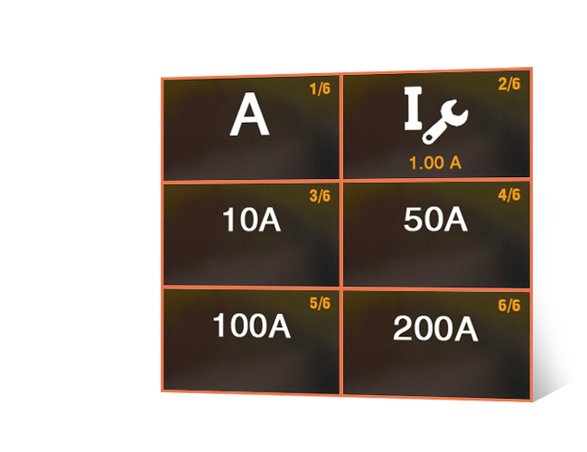
One of the problems during contact resistance measurement with permissible error is availability of oxide films between contact surfaces.
According to international standard IEC 62271-1: Common Specifications for Alternating Current Switchgear and Controlgear (International Electrotechnical Commission), to control this type of error test current amperage during testing the electric resistance in the main circuit of a HV circuit breaker shall be between 50 A and its rated value.
Test current in circuit breakers is often limited by specific values: 100 A and 200 A.
The amperage in MIKO-21 can be set in several ways:
By selecting from a number of specified values: 10 A, 50 A, 100 A, and 200 A;
By setting the automatic mode for selecting test current;
By setting test current manually in the range from 1 A to 200 A at a step of 1 A.
[~DETAIL_TEXT] =>
One of the problems during contact resistance measurement with permissible error is availability of oxide films between contact surfaces.
According to international standard IEC 62271-1: Common Specifications for Alternating Current Switchgear and Controlgear (International Electrotechnical Commission), to control this type of error test current amperage during testing the electric resistance in the main circuit of a HV circuit breaker shall be between 50 A and its rated value.
Test current in circuit breakers is often limited by specific values: 100 A and 200 A.
The amperage in MIKO-21 can be set in several ways:
By selecting from a number of specified values: 10 A, 50 A, 100 A, and 200 A;
By setting the automatic mode for selecting test current;
By setting test current manually in the range from 1 A to 200 A at a step of 1 A.
[SORT] => 20
[~SORT] => 20
[DETAIL_TEXT_TYPE] => html
[~DETAIL_TEXT_TYPE] => html
[PROPERTIES] => Array
(
[PREVIEW_ICON] => Array
(
[ID] => 310
[TIMESTAMP_X] => 2019-11-18 14:18:31
[IBLOCK_ID] => 102
[NAME] => Иконка для анонса
[ACTIVE] => Y
[SORT] => 500
[CODE] => PREVIEW_ICON
[DEFAULT_VALUE] =>
[PROPERTY_TYPE] => F
[ROW_COUNT] => 1
[COL_COUNT] => 50
[LIST_TYPE] => L
[MULTIPLE] => N
[XML_ID] => 28
[FILE_TYPE] => jpg, png, jpeg
[MULTIPLE_CNT] => 5
[TMP_ID] =>
[LINK_IBLOCK_ID] => 0
[WITH_DESCRIPTION] => N
[SEARCHABLE] => N
[FILTRABLE] => N
[IS_REQUIRED] => Y
[VERSION] => 1
[USER_TYPE] =>
[USER_TYPE_SETTINGS] =>
[HINT] =>
[PROPERTY_VALUE_ID] => 32619
[VALUE] => 20569
[DESCRIPTION] =>
[VALUE_ENUM] =>
[VALUE_XML_ID] =>
[VALUE_SORT] =>
[~VALUE] => 20569
[~DESCRIPTION] =>
[~NAME] => Иконка для анонса
[~DEFAULT_VALUE] =>
)
[DETAIL_ICON] => Array
(
[ID] => 311
[TIMESTAMP_X] => 2019-11-18 14:18:31
[IBLOCK_ID] => 102
[NAME] => Иконка для описания
[ACTIVE] => Y
[SORT] => 500
[CODE] => DETAIL_ICON
[DEFAULT_VALUE] =>
[PROPERTY_TYPE] => F
[ROW_COUNT] => 1
[COL_COUNT] => 50
[LIST_TYPE] => L
[MULTIPLE] => N
[XML_ID] => 29
[FILE_TYPE] => jpg, png, jpeg
[MULTIPLE_CNT] => 5
[TMP_ID] =>
[LINK_IBLOCK_ID] => 0
[WITH_DESCRIPTION] => N
[SEARCHABLE] => N
[FILTRABLE] => N
[IS_REQUIRED] => Y
[VERSION] => 1
[USER_TYPE] =>
[USER_TYPE_SETTINGS] =>
[HINT] =>
[PROPERTY_VALUE_ID] => 32620
[VALUE] => 20570
[DESCRIPTION] =>
[VALUE_ENUM] =>
[VALUE_XML_ID] =>
[VALUE_SORT] =>
[~VALUE] => 20570
[~DESCRIPTION] =>
[~NAME] => Иконка для описания
[~DEFAULT_VALUE] =>
)
[MORE_PHOTO] => Array
(
[ID] => 312
[TIMESTAMP_X] => 2019-11-18 14:18:31
[IBLOCK_ID] => 102
[NAME] => Фотографии
[ACTIVE] => Y
[SORT] => 500
[CODE] => MORE_PHOTO
[DEFAULT_VALUE] =>
[PROPERTY_TYPE] => F
[ROW_COUNT] => 1
[COL_COUNT] => 50
[LIST_TYPE] => L
[MULTIPLE] => Y
[XML_ID] => 30
[FILE_TYPE] => jpg, png, jpeg
[MULTIPLE_CNT] => 5
[TMP_ID] =>
[LINK_IBLOCK_ID] => 0
[WITH_DESCRIPTION] => Y
[SEARCHABLE] => N
[FILTRABLE] => N
[IS_REQUIRED] => N
[VERSION] => 1
[USER_TYPE] =>
[USER_TYPE_SETTINGS] =>
[HINT] =>
[PROPERTY_VALUE_ID] =>
[VALUE] =>
[DESCRIPTION] =>
[VALUE_ENUM] =>
[VALUE_XML_ID] =>
[VALUE_SORT] =>
[~VALUE] =>
[~DESCRIPTION] =>
[~NAME] => Фотографии
[~DEFAULT_VALUE] =>
)
)
)
Array
(
    [ID] => 16512
    [~ID] => 16512
    [NAME] => Special algorithms for measuring contact resistance of HV circuit breakers with built-in current transformers (CT)
    [~NAME] => Special algorithms for measuring contact resistance of HV circuit breakers with built-in current transformers (CT)
    [IBLOCK_ID] => 102
    [~IBLOCK_ID] => 102
    [DETAIL_TEXT] =>
	 SKB EP micro-ohmmeters are the only instruments enabling to measure contact resistance of live tank and dead tank circuit breakers using separate automatic modes optimized for those circuit breakers.
Mode 1 makes it possible to carry out measurements in the circuits without CT;
Mode 2 enables to operate measurements in the circuits with CT with minimal battery power consumption;
Mode 3 enables to operate measurement in the circuits with CT using 100 A or 200 A test current (set by a user) without saving battery power.
Current transformers of dead tank circuit breakers form an extended transition process when test current is applied. Due to that measurement time is determined by the parameters of CTs, their number, and test current. For example, for HV oil-blast circuit breakers measurement time may be up to 30 seconds.
MIKO-21 special algorithms with automatic measurement stop prevent subjective errors and increase number of measurements per one battery charge.
[~DETAIL_TEXT] =>
SKB EP micro-ohmmeters are the only instruments enabling to measure contact resistance of live tank and dead tank circuit breakers using separate automatic modes optimized for those circuit breakers.
Mode 1 makes it possible to carry out measurements in the circuits without CT;
Mode 2 enables to operate measurements in the circuits with CT with minimal battery power consumption;
Mode 3 enables to operate measurement in the circuits with CT using 100 A or 200 A test current (set by a user) without saving battery power.
Current transformers of dead tank circuit breakers form an extended transition process when test current is applied. Due to that measurement time is determined by the parameters of CTs, their number, and test current. For example, for HV oil-blast circuit breakers measurement time may be up to 30 seconds.
MIKO-21 special algorithms with automatic measurement stop prevent subjective errors and increase number of measurements per one battery charge.
[SORT] => 30
[~SORT] => 30
[DETAIL_TEXT_TYPE] => html
[~DETAIL_TEXT_TYPE] => html
[PROPERTIES] => Array
(
[PREVIEW_ICON] => Array
(
[ID] => 310
[TIMESTAMP_X] => 2019-11-18 14:18:31
[IBLOCK_ID] => 102
[NAME] => Иконка для анонса
[ACTIVE] => Y
[SORT] => 500
[CODE] => PREVIEW_ICON
[DEFAULT_VALUE] =>
[PROPERTY_TYPE] => F
[ROW_COUNT] => 1
[COL_COUNT] => 50
[LIST_TYPE] => L
[MULTIPLE] => N
[XML_ID] => 28
[FILE_TYPE] => jpg, png, jpeg
[MULTIPLE_CNT] => 5
[TMP_ID] =>
[LINK_IBLOCK_ID] => 0
[WITH_DESCRIPTION] => N
[SEARCHABLE] => N
[FILTRABLE] => N
[IS_REQUIRED] => Y
[VERSION] => 1
[USER_TYPE] =>
[USER_TYPE_SETTINGS] =>
[HINT] =>
[PROPERTY_VALUE_ID] => 32621
[VALUE] => 20572
[DESCRIPTION] =>
[VALUE_ENUM] =>
[VALUE_XML_ID] =>
[VALUE_SORT] =>
[~VALUE] => 20572
[~DESCRIPTION] =>
[~NAME] => Иконка для анонса
[~DEFAULT_VALUE] =>
)
[DETAIL_ICON] => Array
(
[ID] => 311
[TIMESTAMP_X] => 2019-11-18 14:18:31
[IBLOCK_ID] => 102
[NAME] => Иконка для описания
[ACTIVE] => Y
[SORT] => 500
[CODE] => DETAIL_ICON
[DEFAULT_VALUE] =>
[PROPERTY_TYPE] => F
[ROW_COUNT] => 1
[COL_COUNT] => 50
[LIST_TYPE] => L
[MULTIPLE] => N
[XML_ID] => 29
[FILE_TYPE] => jpg, png, jpeg
[MULTIPLE_CNT] => 5
[TMP_ID] =>
[LINK_IBLOCK_ID] => 0
[WITH_DESCRIPTION] => N
[SEARCHABLE] => N
[FILTRABLE] => N
[IS_REQUIRED] => Y
[VERSION] => 1
[USER_TYPE] =>
[USER_TYPE_SETTINGS] =>
[HINT] =>
[PROPERTY_VALUE_ID] => 32622
[VALUE] => 20573
[DESCRIPTION] =>
[VALUE_ENUM] =>
[VALUE_XML_ID] =>
[VALUE_SORT] =>
[~VALUE] => 20573
[~DESCRIPTION] =>
[~NAME] => Иконка для описания
[~DEFAULT_VALUE] =>
)
[MORE_PHOTO] => Array
(
[ID] => 312
[TIMESTAMP_X] => 2019-11-18 14:18:31
[IBLOCK_ID] => 102
[NAME] => Фотографии
[ACTIVE] => Y
[SORT] => 500
[CODE] => MORE_PHOTO
[DEFAULT_VALUE] =>
[PROPERTY_TYPE] => F
[ROW_COUNT] => 1
[COL_COUNT] => 50
[LIST_TYPE] => L
[MULTIPLE] => Y
[XML_ID] => 30
[FILE_TYPE] => jpg, png, jpeg
[MULTIPLE_CNT] => 5
[TMP_ID] =>
[LINK_IBLOCK_ID] => 0
[WITH_DESCRIPTION] => Y
[SEARCHABLE] => N
[FILTRABLE] => N
[IS_REQUIRED] => N
[VERSION] => 1
[USER_TYPE] =>
[USER_TYPE_SETTINGS] =>
[HINT] =>
[PROPERTY_VALUE_ID] =>
[VALUE] =>
[DESCRIPTION] =>
[VALUE_ENUM] =>
[VALUE_XML_ID] =>
[VALUE_SORT] =>
[~VALUE] =>
[~DESCRIPTION] =>
[~NAME] => Фотографии
[~DEFAULT_VALUE] =>
)
)
)
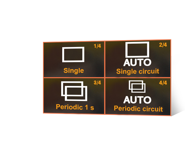
Four ways are programmed in the instrument to start resistance measurement:
Single is started once the cable clamps are contacted to the tested object and followed by pressing the START button.
Auto single circuit is initiated by pressing the START button. The instrument will start measurement when the electric contact between the tested circuit and the test cable contacts is set. The test can be repeated by pressing the START button again.
Periodic is used in pre-specified time intervals when both hands are occupied with cable probes pressing against the test points. The user can choose time interval between the tests. The instrument will work continuously until the user stops the mode.
Auto periodic circuit is initiated by pressing the START button and used for continuous measurements. The user connects the current cable, and as soon as the potential contacts are connected, the measurement will start automatically. To repeat a test, simply break contact with potential probes and reconnect.
[~DETAIL_TEXT] =>
Four ways are programmed in the instrument to start resistance measurement:
Single is started once the cable clamps are contacted to the tested object and followed by pressing the START button.
Auto single circuit is initiated by pressing the START button. The instrument will start measurement when the electric contact between the tested circuit and the test cable contacts is set. The test can be repeated by pressing the START button again.
Periodic is used in pre-specified time intervals when both hands are occupied with cable probes pressing against the test points. The user can choose time interval between the tests. The instrument will work continuously until the user stops the mode.
Auto periodic circuit is initiated by pressing the START button and used for continuous measurements. The user connects the current cable, and as soon as the potential contacts are connected, the measurement will start automatically. To repeat a test, simply break contact with potential probes and reconnect.
[SORT] => 40
[~SORT] => 40
[DETAIL_TEXT_TYPE] => html
[~DETAIL_TEXT_TYPE] => html
[PROPERTIES] => Array
(
[PREVIEW_ICON] => Array
(
[ID] => 310
[TIMESTAMP_X] => 2019-11-18 14:18:31
[IBLOCK_ID] => 102
[NAME] => Иконка для анонса
[ACTIVE] => Y
[SORT] => 500
[CODE] => PREVIEW_ICON
[DEFAULT_VALUE] =>
[PROPERTY_TYPE] => F
[ROW_COUNT] => 1
[COL_COUNT] => 50
[LIST_TYPE] => L
[MULTIPLE] => N
[XML_ID] => 28
[FILE_TYPE] => jpg, png, jpeg
[MULTIPLE_CNT] => 5
[TMP_ID] =>
[LINK_IBLOCK_ID] => 0
[WITH_DESCRIPTION] => N
[SEARCHABLE] => N
[FILTRABLE] => N
[IS_REQUIRED] => Y
[VERSION] => 1
[USER_TYPE] =>
[USER_TYPE_SETTINGS] =>
[HINT] =>
[PROPERTY_VALUE_ID] => 32623
[VALUE] => 20575
[DESCRIPTION] =>
[VALUE_ENUM] =>
[VALUE_XML_ID] =>
[VALUE_SORT] =>
[~VALUE] => 20575
[~DESCRIPTION] =>
[~NAME] => Иконка для анонса
[~DEFAULT_VALUE] =>
)
[DETAIL_ICON] => Array
(
[ID] => 311
[TIMESTAMP_X] => 2019-11-18 14:18:31
[IBLOCK_ID] => 102
[NAME] => Иконка для описания
[ACTIVE] => Y
[SORT] => 500
[CODE] => DETAIL_ICON
[DEFAULT_VALUE] =>
[PROPERTY_TYPE] => F
[ROW_COUNT] => 1
[COL_COUNT] => 50
[LIST_TYPE] => L
[MULTIPLE] => N
[XML_ID] => 29
[FILE_TYPE] => jpg, png, jpeg
[MULTIPLE_CNT] => 5
[TMP_ID] =>
[LINK_IBLOCK_ID] => 0
[WITH_DESCRIPTION] => N
[SEARCHABLE] => N
[FILTRABLE] => N
[IS_REQUIRED] => Y
[VERSION] => 1
[USER_TYPE] =>
[USER_TYPE_SETTINGS] =>
[HINT] =>
[PROPERTY_VALUE_ID] => 32624
[VALUE] => 20576
[DESCRIPTION] =>
[VALUE_ENUM] =>
[VALUE_XML_ID] =>
[VALUE_SORT] =>
[~VALUE] => 20576
[~DESCRIPTION] =>
[~NAME] => Иконка для описания
[~DEFAULT_VALUE] =>
)
[MORE_PHOTO] => Array
(
[ID] => 312
[TIMESTAMP_X] => 2019-11-18 14:18:31
[IBLOCK_ID] => 102
[NAME] => Фотографии
[ACTIVE] => Y
[SORT] => 500
[CODE] => MORE_PHOTO
[DEFAULT_VALUE] =>
[PROPERTY_TYPE] => F
[ROW_COUNT] => 1
[COL_COUNT] => 50
[LIST_TYPE] => L
[MULTIPLE] => Y
[XML_ID] => 30
[FILE_TYPE] => jpg, png, jpeg
[MULTIPLE_CNT] => 5
[TMP_ID] =>
[LINK_IBLOCK_ID] => 0
[WITH_DESCRIPTION] => Y
[SEARCHABLE] => N
[FILTRABLE] => N
[IS_REQUIRED] => N
[VERSION] => 1
[USER_TYPE] =>
[USER_TYPE_SETTINGS] =>
[HINT] =>
[PROPERTY_VALUE_ID] =>
[VALUE] =>
[DESCRIPTION] =>
[VALUE_ENUM] =>
[VALUE_XML_ID] =>
[VALUE_SORT] =>
[~VALUE] =>
[~DESCRIPTION] =>
[~NAME] => Фотографии
[~DEFAULT_VALUE] =>
)
)
)
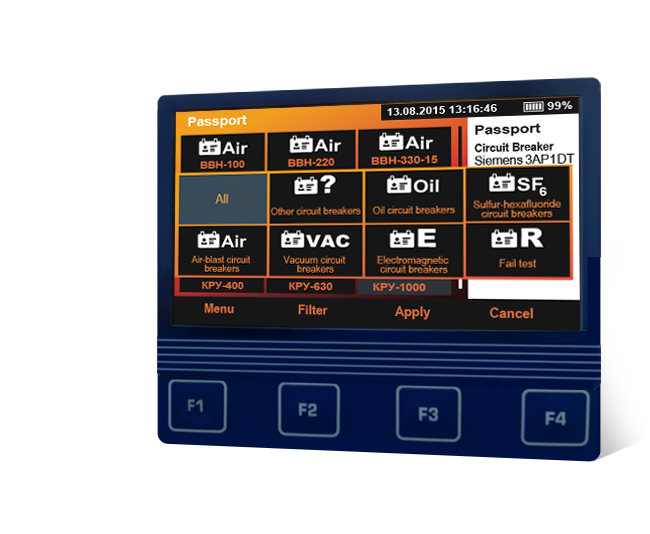
The instrument contains a built-in database that contains nominal values of high-voltage circuit breakers indicating the maximum and/or minimum permissible values of contact resistance. There are also the nominal values for rejected resistors indicating the acceptable values of the upper and lower thresholds of resistance.
The user can add / edit / delete the nominal values of the exact measured object.
[~DETAIL_TEXT] =>
The instrument contains a built-in database that contains nominal values of high-voltage circuit breakers indicating the maximum and/or minimum permissible values of contact resistance. There are also the nominal values for rejected resistors indicating the acceptable values of the upper and lower thresholds of resistance.
The user can add / edit / delete the nominal values of the exact measured object.
[SORT] => 50
[~SORT] => 50
[DETAIL_TEXT_TYPE] => html
[~DETAIL_TEXT_TYPE] => html
[PROPERTIES] => Array
(
[PREVIEW_ICON] => Array
(
[ID] => 310
[TIMESTAMP_X] => 2019-11-18 14:18:31
[IBLOCK_ID] => 102
[NAME] => Иконка для анонса
[ACTIVE] => Y
[SORT] => 500
[CODE] => PREVIEW_ICON
[DEFAULT_VALUE] =>
[PROPERTY_TYPE] => F
[ROW_COUNT] => 1
[COL_COUNT] => 50
[LIST_TYPE] => L
[MULTIPLE] => N
[XML_ID] => 28
[FILE_TYPE] => jpg, png, jpeg
[MULTIPLE_CNT] => 5
[TMP_ID] =>
[LINK_IBLOCK_ID] => 0
[WITH_DESCRIPTION] => N
[SEARCHABLE] => N
[FILTRABLE] => N
[IS_REQUIRED] => Y
[VERSION] => 1
[USER_TYPE] =>
[USER_TYPE_SETTINGS] =>
[HINT] =>
[PROPERTY_VALUE_ID] => 32625
[VALUE] => 20578
[DESCRIPTION] =>
[VALUE_ENUM] =>
[VALUE_XML_ID] =>
[VALUE_SORT] =>
[~VALUE] => 20578
[~DESCRIPTION] =>
[~NAME] => Иконка для анонса
[~DEFAULT_VALUE] =>
)
[DETAIL_ICON] => Array
(
[ID] => 311
[TIMESTAMP_X] => 2019-11-18 14:18:31
[IBLOCK_ID] => 102
[NAME] => Иконка для описания
[ACTIVE] => Y
[SORT] => 500
[CODE] => DETAIL_ICON
[DEFAULT_VALUE] =>
[PROPERTY_TYPE] => F
[ROW_COUNT] => 1
[COL_COUNT] => 50
[LIST_TYPE] => L
[MULTIPLE] => N
[XML_ID] => 29
[FILE_TYPE] => jpg, png, jpeg
[MULTIPLE_CNT] => 5
[TMP_ID] =>
[LINK_IBLOCK_ID] => 0
[WITH_DESCRIPTION] => N
[SEARCHABLE] => N
[FILTRABLE] => N
[IS_REQUIRED] => Y
[VERSION] => 1
[USER_TYPE] =>
[USER_TYPE_SETTINGS] =>
[HINT] =>
[PROPERTY_VALUE_ID] => 32626
[VALUE] => 20579
[DESCRIPTION] =>
[VALUE_ENUM] =>
[VALUE_XML_ID] =>
[VALUE_SORT] =>
[~VALUE] => 20579
[~DESCRIPTION] =>
[~NAME] => Иконка для описания
[~DEFAULT_VALUE] =>
)
[MORE_PHOTO] => Array
(
[ID] => 312
[TIMESTAMP_X] => 2019-11-18 14:18:31
[IBLOCK_ID] => 102
[NAME] => Фотографии
[ACTIVE] => Y
[SORT] => 500
[CODE] => MORE_PHOTO
[DEFAULT_VALUE] =>
[PROPERTY_TYPE] => F
[ROW_COUNT] => 1
[COL_COUNT] => 50
[LIST_TYPE] => L
[MULTIPLE] => Y
[XML_ID] => 30
[FILE_TYPE] => jpg, png, jpeg
[MULTIPLE_CNT] => 5
[TMP_ID] =>
[LINK_IBLOCK_ID] => 0
[WITH_DESCRIPTION] => Y
[SEARCHABLE] => N
[FILTRABLE] => N
[IS_REQUIRED] => N
[VERSION] => 1
[USER_TYPE] =>
[USER_TYPE_SETTINGS] =>
[HINT] =>
[PROPERTY_VALUE_ID] =>
[VALUE] =>
[DESCRIPTION] =>
[VALUE_ENUM] =>
[VALUE_XML_ID] =>
[VALUE_SORT] =>
[~VALUE] =>
[~DESCRIPTION] =>
[~NAME] => Фотографии
[~DEFAULT_VALUE] =>
)
)
)
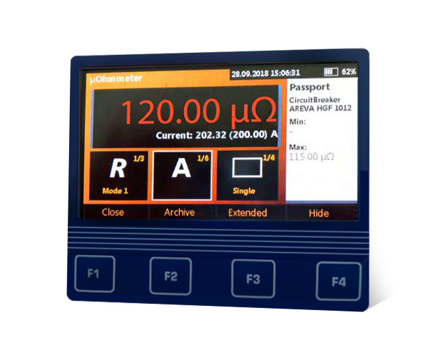
Availability of a built-in archive of nominal values of electric resistances (main circuit resistance of HV circuit breakers) facilitates automatic detection, and once the measured value exceeds the nominal value it is highlighted with red colour.
This mechanism works due to either the built-in database of nominal values or the ability to add / edit / delete the nominal data of the measured object independently.
[~DETAIL_TEXT] =>
Availability of a built-in archive of nominal values of electric resistances (main circuit resistance of HV circuit breakers) facilitates automatic detection, and once the measured value exceeds the nominal value it is highlighted with red colour.
This mechanism works due to either the built-in database of nominal values or the ability to add / edit / delete the nominal data of the measured object independently.
[SORT] => 60
[~SORT] => 60
[DETAIL_TEXT_TYPE] => html
[~DETAIL_TEXT_TYPE] => html
[PROPERTIES] => Array
(
[PREVIEW_ICON] => Array
(
[ID] => 310
[TIMESTAMP_X] => 2019-11-18 14:18:31
[IBLOCK_ID] => 102
[NAME] => Иконка для анонса
[ACTIVE] => Y
[SORT] => 500
[CODE] => PREVIEW_ICON
[DEFAULT_VALUE] =>
[PROPERTY_TYPE] => F
[ROW_COUNT] => 1
[COL_COUNT] => 50
[LIST_TYPE] => L
[MULTIPLE] => N
[XML_ID] => 28
[FILE_TYPE] => jpg, png, jpeg
[MULTIPLE_CNT] => 5
[TMP_ID] =>
[LINK_IBLOCK_ID] => 0
[WITH_DESCRIPTION] => N
[SEARCHABLE] => N
[FILTRABLE] => N
[IS_REQUIRED] => Y
[VERSION] => 1
[USER_TYPE] =>
[USER_TYPE_SETTINGS] =>
[HINT] =>
[PROPERTY_VALUE_ID] => 32627
[VALUE] => 20581
[DESCRIPTION] =>
[VALUE_ENUM] =>
[VALUE_XML_ID] =>
[VALUE_SORT] =>
[~VALUE] => 20581
[~DESCRIPTION] =>
[~NAME] => Иконка для анонса
[~DEFAULT_VALUE] =>
)
[DETAIL_ICON] => Array
(
[ID] => 311
[TIMESTAMP_X] => 2019-11-18 14:18:31
[IBLOCK_ID] => 102
[NAME] => Иконка для описания
[ACTIVE] => Y
[SORT] => 500
[CODE] => DETAIL_ICON
[DEFAULT_VALUE] =>
[PROPERTY_TYPE] => F
[ROW_COUNT] => 1
[COL_COUNT] => 50
[LIST_TYPE] => L
[MULTIPLE] => N
[XML_ID] => 29
[FILE_TYPE] => jpg, png, jpeg
[MULTIPLE_CNT] => 5
[TMP_ID] =>
[LINK_IBLOCK_ID] => 0
[WITH_DESCRIPTION] => N
[SEARCHABLE] => N
[FILTRABLE] => N
[IS_REQUIRED] => Y
[VERSION] => 1
[USER_TYPE] =>
[USER_TYPE_SETTINGS] =>
[HINT] =>
[PROPERTY_VALUE_ID] => 32628
[VALUE] => 20582
[DESCRIPTION] =>
[VALUE_ENUM] =>
[VALUE_XML_ID] =>
[VALUE_SORT] =>
[~VALUE] => 20582
[~DESCRIPTION] =>
[~NAME] => Иконка для описания
[~DEFAULT_VALUE] =>
)
[MORE_PHOTO] => Array
(
[ID] => 312
[TIMESTAMP_X] => 2019-11-18 14:18:31
[IBLOCK_ID] => 102
[NAME] => Фотографии
[ACTIVE] => Y
[SORT] => 500
[CODE] => MORE_PHOTO
[DEFAULT_VALUE] =>
[PROPERTY_TYPE] => F
[ROW_COUNT] => 1
[COL_COUNT] => 50
[LIST_TYPE] => L
[MULTIPLE] => Y
[XML_ID] => 30
[FILE_TYPE] => jpg, png, jpeg
[MULTIPLE_CNT] => 5
[TMP_ID] =>
[LINK_IBLOCK_ID] => 0
[WITH_DESCRIPTION] => Y
[SEARCHABLE] => N
[FILTRABLE] => N
[IS_REQUIRED] => N
[VERSION] => 1
[USER_TYPE] =>
[USER_TYPE_SETTINGS] =>
[HINT] =>
[PROPERTY_VALUE_ID] =>
[VALUE] =>
[DESCRIPTION] =>
[VALUE_ENUM] =>
[VALUE_XML_ID] =>
[VALUE_SORT] =>
[~VALUE] =>
[~DESCRIPTION] =>
[~NAME] => Фотографии
[~DEFAULT_VALUE] =>
)
)
)
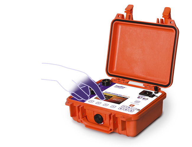
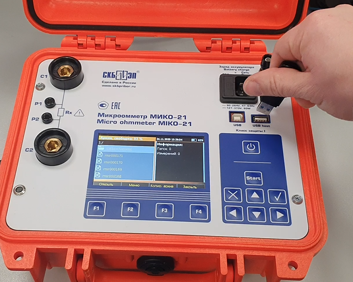
Color graphic display of high brightness ensures easy reading on a sunny day, whereas intuitively understandable interface with a multi-sensor display simplifies the instrument use.
The Instrument can be manipulated either from the keyboard or from the multi-sensor display, as suits.
Communication with PC via USB or a flash card facilitates data transfer from the Instrument to the company data base. The device can be integrated into measuring systems under PC control of diagnostic laboratories and companies producing electric equipment.
[~DETAIL_TEXT] =>
Color graphic display of high brightness ensures easy reading on a sunny day, whereas intuitively understandable interface with a multi-sensor display simplifies the instrument use.
The Instrument can be manipulated either from the keyboard or from the multi-sensor display, as suits.
Communication with PC via USB or a flash card facilitates data transfer from the Instrument to the company data base. The device can be integrated into measuring systems under PC control of diagnostic laboratories and companies producing electric equipment.
[SORT] => 70
[~SORT] => 70
[DETAIL_TEXT_TYPE] => html
[~DETAIL_TEXT_TYPE] => html
[PROPERTIES] => Array
(
[PREVIEW_ICON] => Array
(
[ID] => 310
[TIMESTAMP_X] => 2019-11-18 14:18:31
[IBLOCK_ID] => 102
[NAME] => Иконка для анонса
[ACTIVE] => Y
[SORT] => 500
[CODE] => PREVIEW_ICON
[DEFAULT_VALUE] =>
[PROPERTY_TYPE] => F
[ROW_COUNT] => 1
[COL_COUNT] => 50
[LIST_TYPE] => L
[MULTIPLE] => N
[XML_ID] => 28
[FILE_TYPE] => jpg, png, jpeg
[MULTIPLE_CNT] => 5
[TMP_ID] =>
[LINK_IBLOCK_ID] => 0
[WITH_DESCRIPTION] => N
[SEARCHABLE] => N
[FILTRABLE] => N
[IS_REQUIRED] => Y
[VERSION] => 1
[USER_TYPE] =>
[USER_TYPE_SETTINGS] =>
[HINT] =>
[PROPERTY_VALUE_ID] => 32629
[VALUE] => 20584
[DESCRIPTION] =>
[VALUE_ENUM] =>
[VALUE_XML_ID] =>
[VALUE_SORT] =>
[~VALUE] => 20584
[~DESCRIPTION] =>
[~NAME] => Иконка для анонса
[~DEFAULT_VALUE] =>
)
[DETAIL_ICON] => Array
(
[ID] => 311
[TIMESTAMP_X] => 2019-11-18 14:18:31
[IBLOCK_ID] => 102
[NAME] => Иконка для описания
[ACTIVE] => Y
[SORT] => 500
[CODE] => DETAIL_ICON
[DEFAULT_VALUE] =>
[PROPERTY_TYPE] => F
[ROW_COUNT] => 1
[COL_COUNT] => 50
[LIST_TYPE] => L
[MULTIPLE] => N
[XML_ID] => 29
[FILE_TYPE] => jpg, png, jpeg
[MULTIPLE_CNT] => 5
[TMP_ID] =>
[LINK_IBLOCK_ID] => 0
[WITH_DESCRIPTION] => N
[SEARCHABLE] => N
[FILTRABLE] => N
[IS_REQUIRED] => Y
[VERSION] => 1
[USER_TYPE] =>
[USER_TYPE_SETTINGS] =>
[HINT] =>
[PROPERTY_VALUE_ID] => 32630
[VALUE] => 20585
[DESCRIPTION] =>
[VALUE_ENUM] =>
[VALUE_XML_ID] =>
[VALUE_SORT] =>
[~VALUE] => 20585
[~DESCRIPTION] =>
[~NAME] => Иконка для описания
[~DEFAULT_VALUE] =>
)
[MORE_PHOTO] => Array
(
[ID] => 312
[TIMESTAMP_X] => 2019-11-18 14:18:31
[IBLOCK_ID] => 102
[NAME] => Фотографии
[ACTIVE] => Y
[SORT] => 500
[CODE] => MORE_PHOTO
[DEFAULT_VALUE] =>
[PROPERTY_TYPE] => F
[ROW_COUNT] => 1
[COL_COUNT] => 50
[LIST_TYPE] => L
[MULTIPLE] => Y
[XML_ID] => 30
[FILE_TYPE] => jpg, png, jpeg
[MULTIPLE_CNT] => 5
[TMP_ID] =>
[LINK_IBLOCK_ID] => 0
[WITH_DESCRIPTION] => Y
[SEARCHABLE] => N
[FILTRABLE] => N
[IS_REQUIRED] => N
[VERSION] => 1
[USER_TYPE] =>
[USER_TYPE_SETTINGS] =>
[HINT] =>
[PROPERTY_VALUE_ID] =>
[VALUE] =>
[DESCRIPTION] =>
[VALUE_ENUM] =>
[VALUE_XML_ID] =>
[VALUE_SORT] =>
[~VALUE] =>
[~DESCRIPTION] =>
[~NAME] => Фотографии
[~DEFAULT_VALUE] =>
)
)
)
Array
(
[ID] => 16517
[~ID] => 16517
[NAME] => Battery-operated power supply, light weight and size
[~NAME] => Battery-operated power supply, light weight and size
[IBLOCK_ID] => 102
[~IBLOCK_ID] => 102
[DETAIL_TEXT] =>
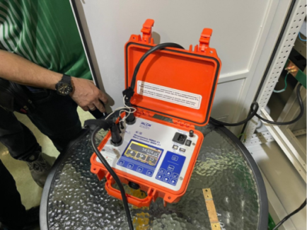
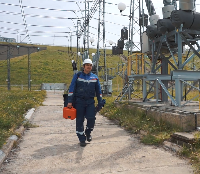
Battery power, low weight and small dimensions ensure complete independence and high mobility of the device in the vast territory of the substation or workshop, and the built-in memory for 2,000 measurements greatly simplifies the process of diagnostics and data transfer from the substation into the company office.
[~DETAIL_TEXT] =>
Battery power, low weight and small dimensions ensure complete independence and high mobility of the device in the vast territory of the substation or workshop, and the built-in memory for 2,000 measurements greatly simplifies the process of diagnostics and data transfer from the substation into the company office.
[SORT] => 80
[~SORT] => 80
[DETAIL_TEXT_TYPE] => html
[~DETAIL_TEXT_TYPE] => html
[PROPERTIES] => Array
(
[PREVIEW_ICON] => Array
(
[ID] => 310
[TIMESTAMP_X] => 2019-11-18 14:18:31
[IBLOCK_ID] => 102
[NAME] => Иконка для анонса
[ACTIVE] => Y
[SORT] => 500
[CODE] => PREVIEW_ICON
[DEFAULT_VALUE] =>
[PROPERTY_TYPE] => F
[ROW_COUNT] => 1
[COL_COUNT] => 50
[LIST_TYPE] => L
[MULTIPLE] => N
[XML_ID] => 28
[FILE_TYPE] => jpg, png, jpeg
[MULTIPLE_CNT] => 5
[TMP_ID] =>
[LINK_IBLOCK_ID] => 0
[WITH_DESCRIPTION] => N
[SEARCHABLE] => N
[FILTRABLE] => N
[IS_REQUIRED] => Y
[VERSION] => 1
[USER_TYPE] =>
[USER_TYPE_SETTINGS] =>
[HINT] =>
[PROPERTY_VALUE_ID] => 32631
[VALUE] => 20587
[DESCRIPTION] =>
[VALUE_ENUM] =>
[VALUE_XML_ID] =>
[VALUE_SORT] =>
[~VALUE] => 20587
[~DESCRIPTION] =>
[~NAME] => Иконка для анонса
[~DEFAULT_VALUE] =>
)
[DETAIL_ICON] => Array
(
[ID] => 311
[TIMESTAMP_X] => 2019-11-18 14:18:31
[IBLOCK_ID] => 102
[NAME] => Иконка для описания
[ACTIVE] => Y
[SORT] => 500
[CODE] => DETAIL_ICON
[DEFAULT_VALUE] =>
[PROPERTY_TYPE] => F
[ROW_COUNT] => 1
[COL_COUNT] => 50
[LIST_TYPE] => L
[MULTIPLE] => N
[XML_ID] => 29
[FILE_TYPE] => jpg, png, jpeg
[MULTIPLE_CNT] => 5
[TMP_ID] =>
[LINK_IBLOCK_ID] => 0
[WITH_DESCRIPTION] => N
[SEARCHABLE] => N
[FILTRABLE] => N
[IS_REQUIRED] => Y
[VERSION] => 1
[USER_TYPE] =>
[USER_TYPE_SETTINGS] =>
[HINT] =>
[PROPERTY_VALUE_ID] => 32632
[VALUE] => 20588
[DESCRIPTION] =>
[VALUE_ENUM] =>
[VALUE_XML_ID] =>
[VALUE_SORT] =>
[~VALUE] => 20588
[~DESCRIPTION] =>
[~NAME] => Иконка для описания
[~DEFAULT_VALUE] =>
)
[MORE_PHOTO] => Array
(
[ID] => 312
[TIMESTAMP_X] => 2019-11-18 14:18:31
[IBLOCK_ID] => 102
[NAME] => Фотографии
[ACTIVE] => Y
[SORT] => 500
[CODE] => MORE_PHOTO
[DEFAULT_VALUE] =>
[PROPERTY_TYPE] => F
[ROW_COUNT] => 1
[COL_COUNT] => 50
[LIST_TYPE] => L
[MULTIPLE] => Y
[XML_ID] => 30
[FILE_TYPE] => jpg, png, jpeg
[MULTIPLE_CNT] => 5
[TMP_ID] =>
[LINK_IBLOCK_ID] => 0
[WITH_DESCRIPTION] => Y
[SEARCHABLE] => N
[FILTRABLE] => N
[IS_REQUIRED] => N
[VERSION] => 1
[USER_TYPE] =>
[USER_TYPE_SETTINGS] =>
[HINT] =>
[PROPERTY_VALUE_ID] =>
[VALUE] =>
[DESCRIPTION] =>
[VALUE_ENUM] =>
[VALUE_XML_ID] =>
[VALUE_SORT] =>
[~VALUE] =>
[~DESCRIPTION] =>
[~NAME] => Фотографии
[~DEFAULT_VALUE] =>
)
)
)
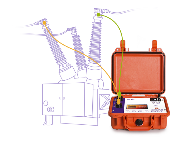
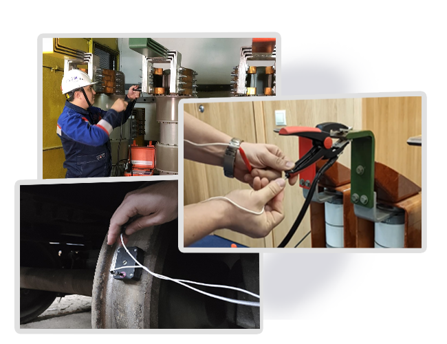
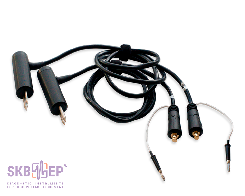
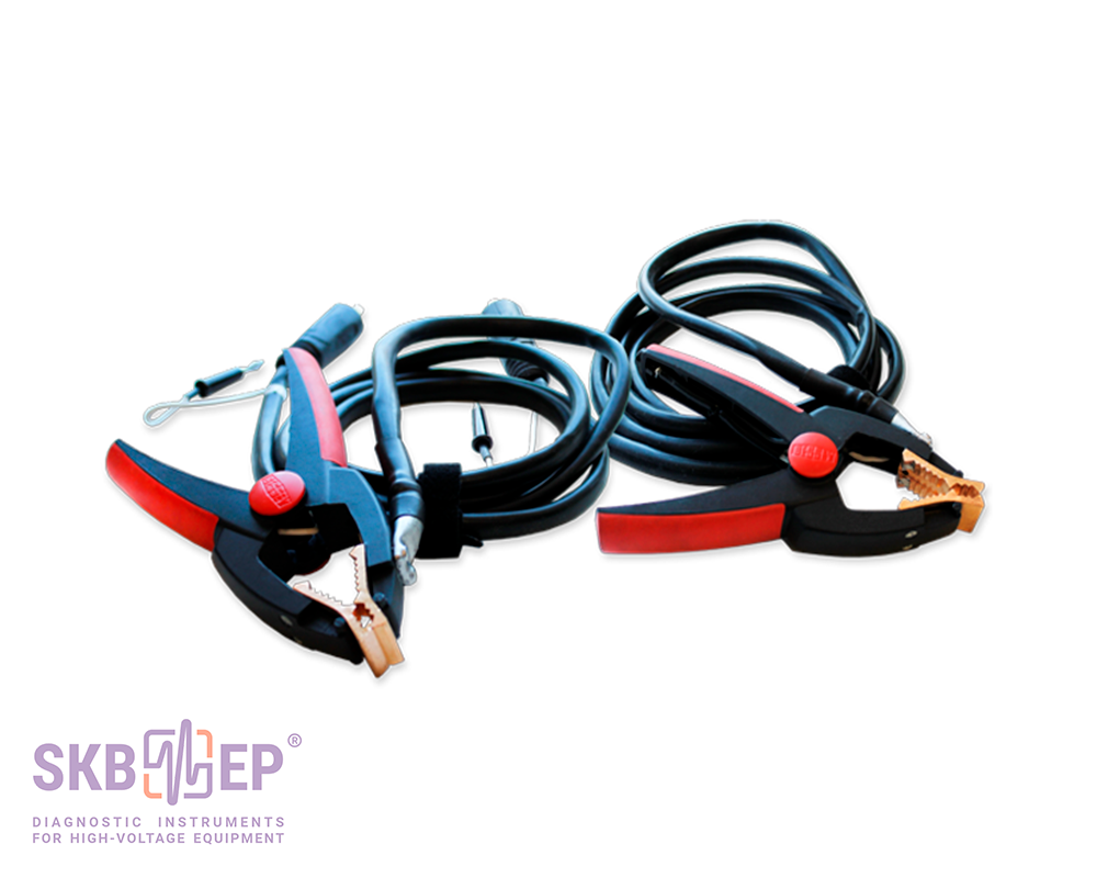
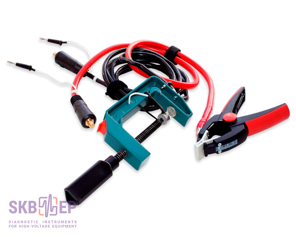
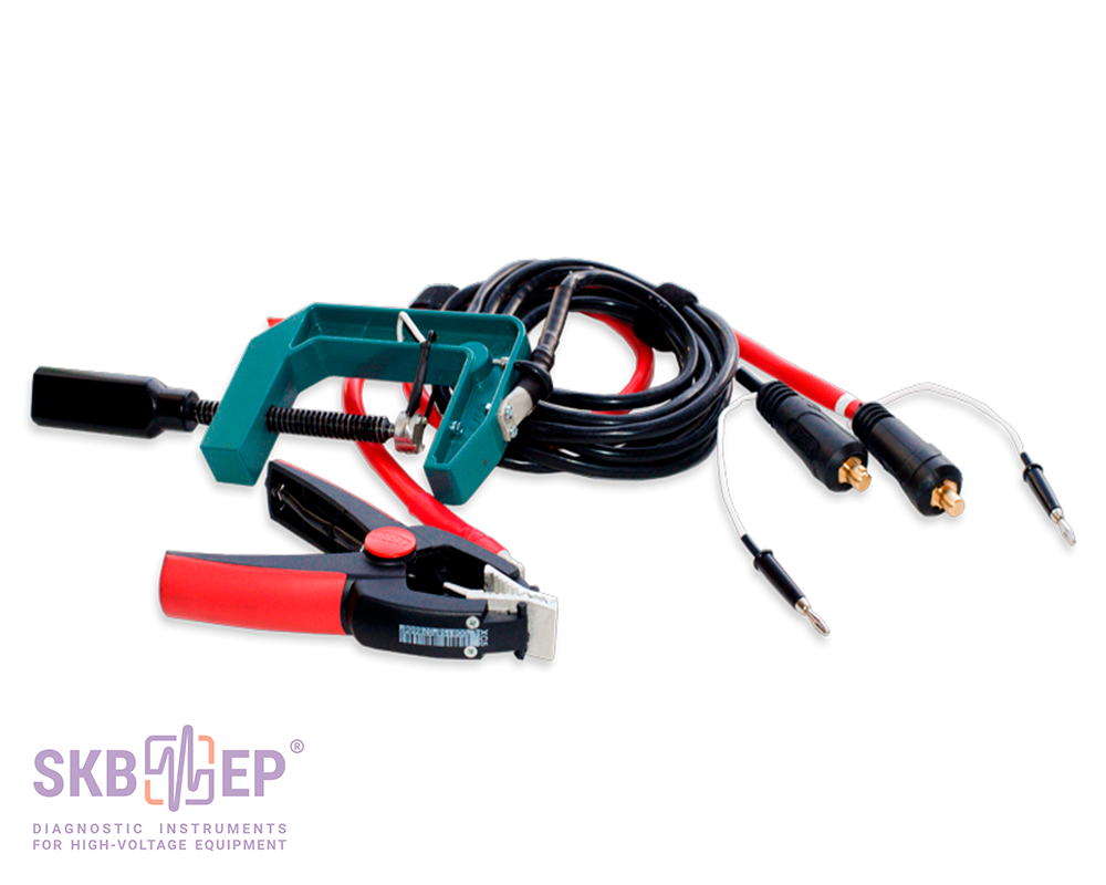
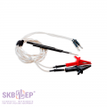
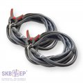
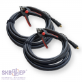
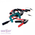
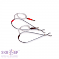
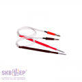
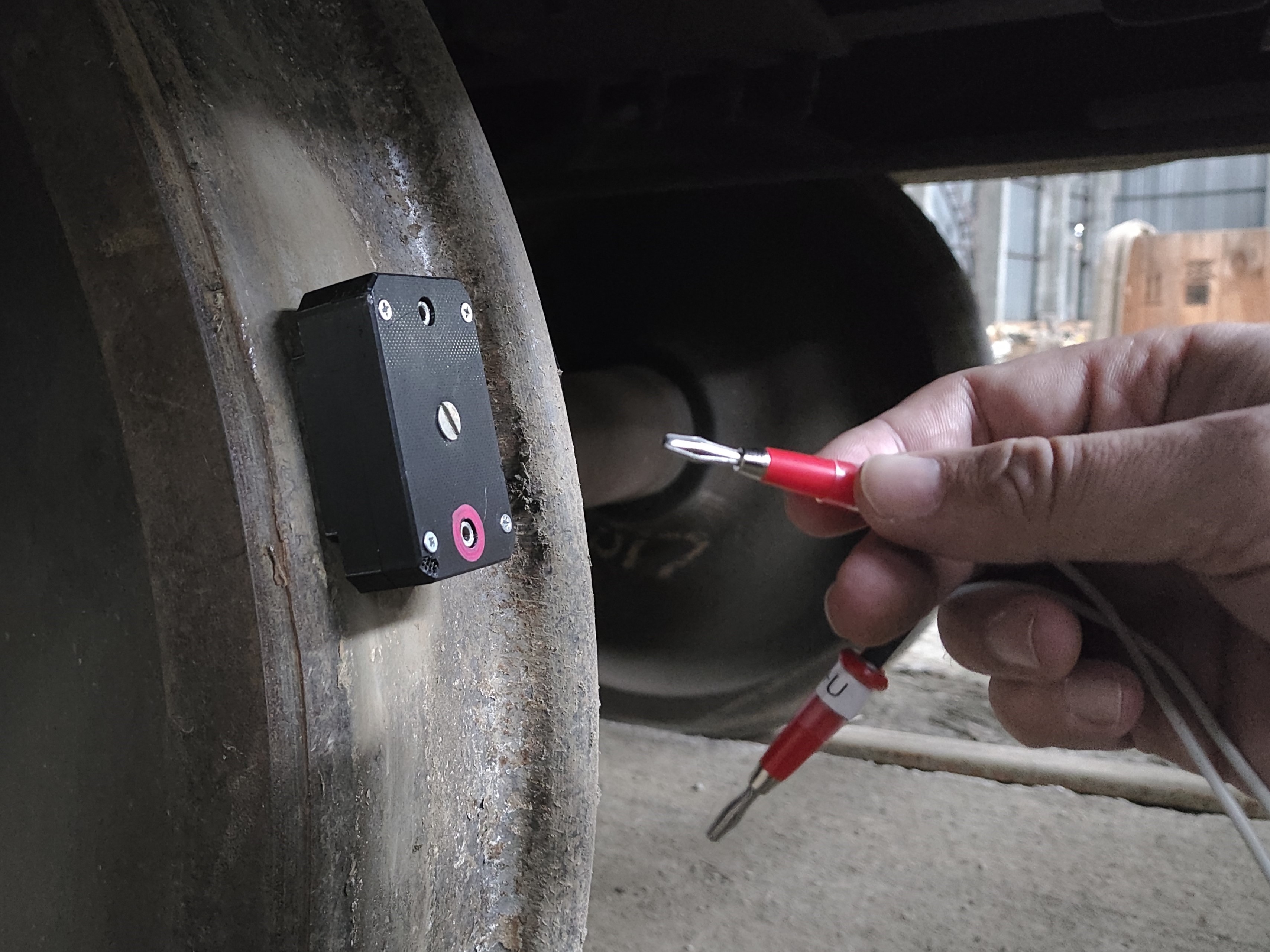
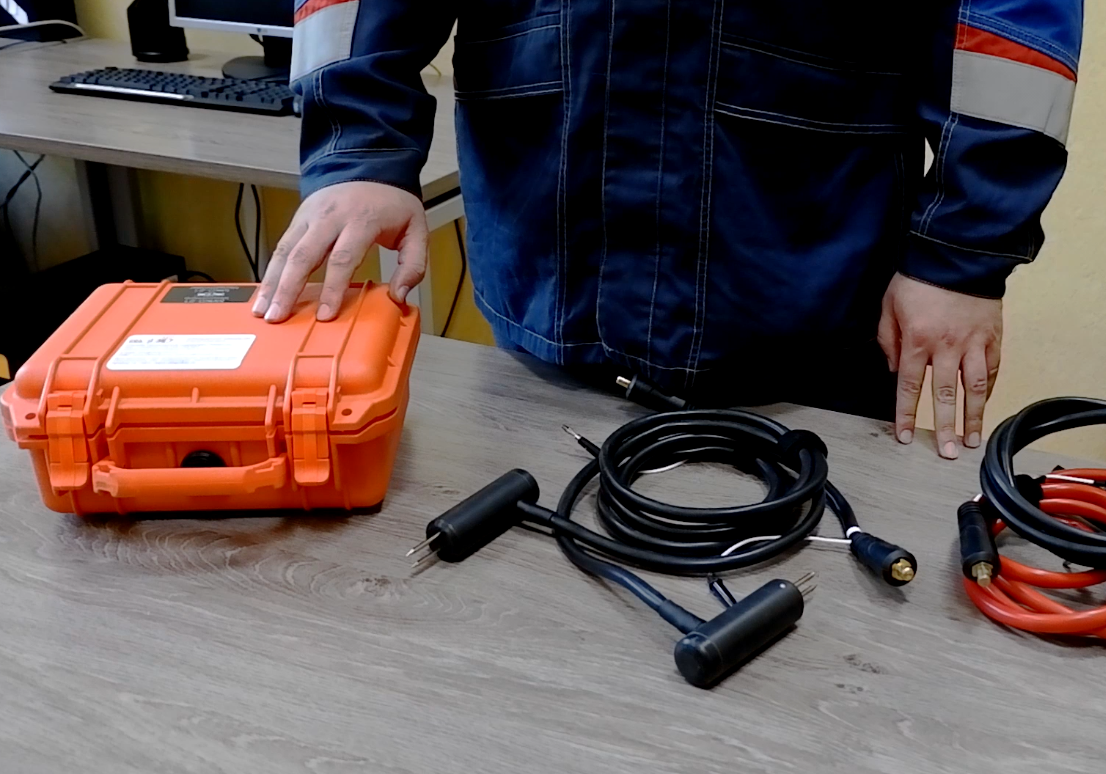
For convenient connection to the object, there are special test cables of different lengths and different types of clamps:
Test cables with Kelvin clamps 2 m long (standard complete set) for high voltage circuit breakers up to 10 kV;
Test cables with Kelvin double hand spikes 1.5 m long for measurement in pipelines and interrupting chambers (recommended when the device is placed near the circuit breaker);
Test cables with Kelvin C-clamps 4.5 m and 6 m long (recommended when the device is placed near the circuit breaker) for circuit breakers from 10 kV to 220 kV;
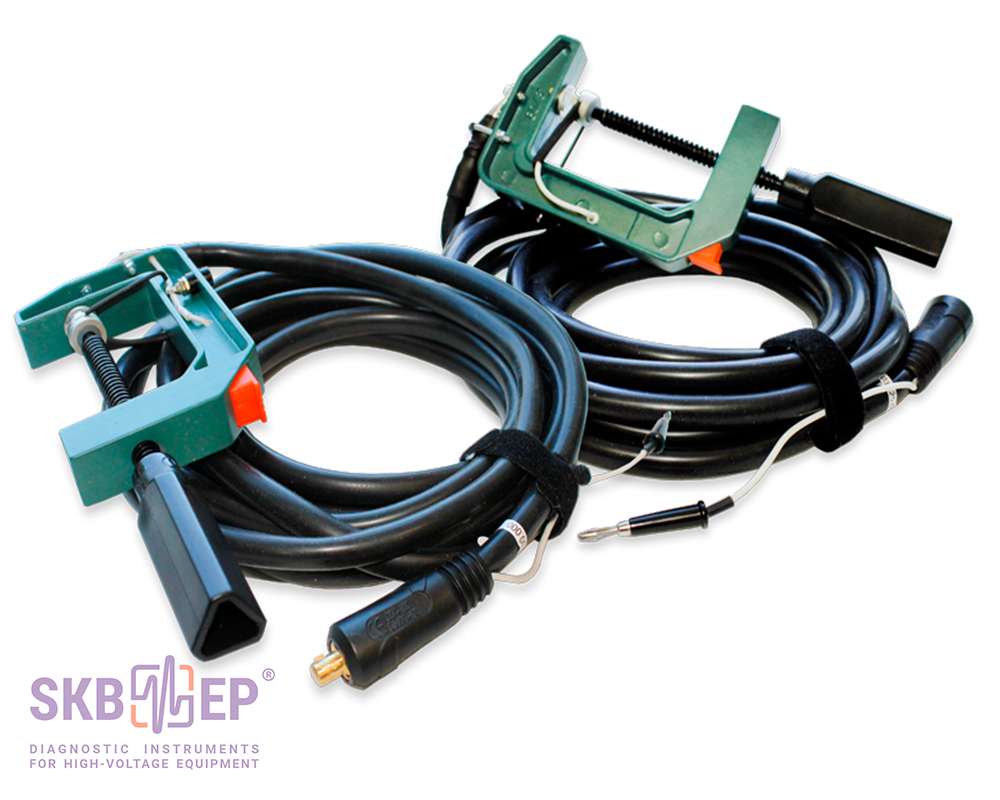
Test cables that consist of a cable with Kelvin clamp and Kelvin C-clamp 3 m, 6 m or 9 m long (recommended when the device is places in a cradle of a lift) for circuit breakers from 220 kV to 750 kV;
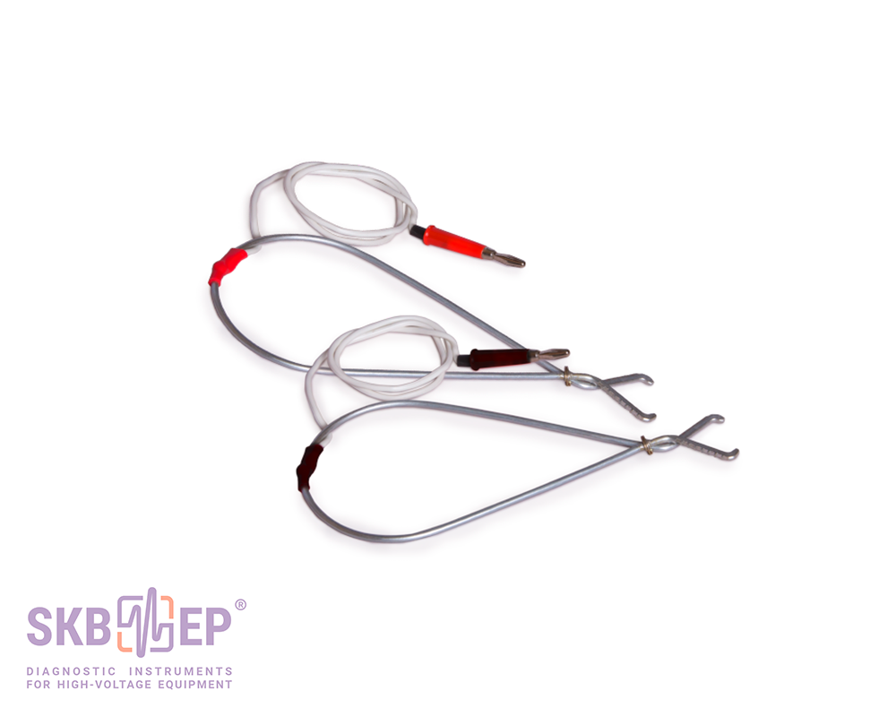
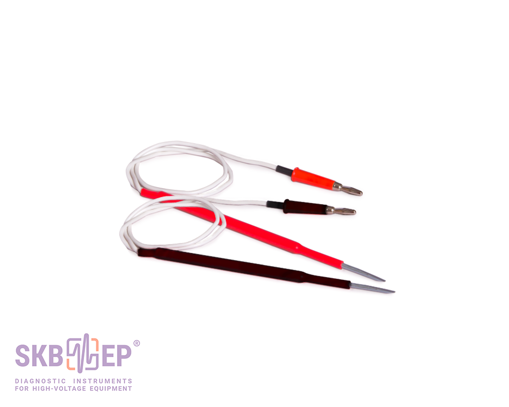
Test cable for precise measurements and measurements on sections of the electric circuit, to the end points of which the test current is applied.
[~DETAIL_TEXT] =>
For convenient connection to the object, there are special test cables of different lengths and different types of clamps:
Test cables with Kelvin clamps 2 m long (standard complete set) for high voltage circuit breakers up to 10 kV;
Test cables with Kelvin double hand spikes 1.5 m long for measurement in pipelines and interrupting chambers (recommended when the device is placed near the circuit breaker);
Test cables with Kelvin C-clamps 4.5 m and 6 m long (recommended when the device is placed near the circuit breaker) for circuit breakers from 10 kV to 220 kV;
Test cables that consist of a cable with Kelvin clamp and Kelvin C-clamp 3 m, 6 m or 9 m long (recommended when the device is places in a cradle of a lift) for circuit breakers from 220 kV to 750 kV;
Test cable for precise measurements and measurements on sections of the electric circuit, to the end points of which the test current is applied.
[SORT] => 90
[~SORT] => 90
[DETAIL_TEXT_TYPE] => html
[~DETAIL_TEXT_TYPE] => html
[PROPERTIES] => Array
(
[PREVIEW_ICON] => Array
(
[ID] => 310
[TIMESTAMP_X] => 2019-11-18 14:18:31
[IBLOCK_ID] => 102
[NAME] => Иконка для анонса
[ACTIVE] => Y
[SORT] => 500
[CODE] => PREVIEW_ICON
[DEFAULT_VALUE] =>
[PROPERTY_TYPE] => F
[ROW_COUNT] => 1
[COL_COUNT] => 50
[LIST_TYPE] => L
[MULTIPLE] => N
[XML_ID] => 28
[FILE_TYPE] => jpg, png, jpeg
[MULTIPLE_CNT] => 5
[TMP_ID] =>
[LINK_IBLOCK_ID] => 0
[WITH_DESCRIPTION] => N
[SEARCHABLE] => N
[FILTRABLE] => N
[IS_REQUIRED] => Y
[VERSION] => 1
[USER_TYPE] =>
[USER_TYPE_SETTINGS] =>
[HINT] =>
[PROPERTY_VALUE_ID] => 32633
[VALUE] => 20590
[DESCRIPTION] =>
[VALUE_ENUM] =>
[VALUE_XML_ID] =>
[VALUE_SORT] =>
[~VALUE] => 20590
[~DESCRIPTION] =>
[~NAME] => Иконка для анонса
[~DEFAULT_VALUE] =>
)
[DETAIL_ICON] => Array
(
[ID] => 311
[TIMESTAMP_X] => 2019-11-18 14:18:31
[IBLOCK_ID] => 102
[NAME] => Иконка для описания
[ACTIVE] => Y
[SORT] => 500
[CODE] => DETAIL_ICON
[DEFAULT_VALUE] =>
[PROPERTY_TYPE] => F
[ROW_COUNT] => 1
[COL_COUNT] => 50
[LIST_TYPE] => L
[MULTIPLE] => N
[XML_ID] => 29
[FILE_TYPE] => jpg, png, jpeg
[MULTIPLE_CNT] => 5
[TMP_ID] =>
[LINK_IBLOCK_ID] => 0
[WITH_DESCRIPTION] => N
[SEARCHABLE] => N
[FILTRABLE] => N
[IS_REQUIRED] => Y
[VERSION] => 1
[USER_TYPE] =>
[USER_TYPE_SETTINGS] =>
[HINT] =>
[PROPERTY_VALUE_ID] => 32634
[VALUE] => 20591
[DESCRIPTION] =>
[VALUE_ENUM] =>
[VALUE_XML_ID] =>
[VALUE_SORT] =>
[~VALUE] => 20591
[~DESCRIPTION] =>
[~NAME] => Иконка для описания
[~DEFAULT_VALUE] =>
)
[MORE_PHOTO] => Array
(
[ID] => 312
[TIMESTAMP_X] => 2019-11-18 14:18:31
[IBLOCK_ID] => 102
[NAME] => Фотографии
[ACTIVE] => Y
[SORT] => 500
[CODE] => MORE_PHOTO
[DEFAULT_VALUE] =>
[PROPERTY_TYPE] => F
[ROW_COUNT] => 1
[COL_COUNT] => 50
[LIST_TYPE] => L
[MULTIPLE] => Y
[XML_ID] => 30
[FILE_TYPE] => jpg, png, jpeg
[MULTIPLE_CNT] => 5
[TMP_ID] =>
[LINK_IBLOCK_ID] => 0
[WITH_DESCRIPTION] => Y
[SEARCHABLE] => N
[FILTRABLE] => N
[IS_REQUIRED] => N
[VERSION] => 1
[USER_TYPE] =>
[USER_TYPE_SETTINGS] =>
[HINT] =>
[PROPERTY_VALUE_ID] => Array
(
[0] => 49700
[1] => 49701
[2] => 49702
[3] => 49703
[4] => 49704
[5] => 49705
[6] => 49706
[7] => 49707
[8] => 49708
[9] => 49709
)
[VALUE] => Array
(
[0] => 27968
[1] => 27969
[2] => 27970
[3] => 27971
[4] => 27972
[5] => 27973
[6] => 27974
[7] => 27975
[8] => 27976
[9] => 27977
)
[DESCRIPTION] => Array
(
[0] => Set #1 (on order)
[1] => Set #2 (2 m, standard complete set)
[2] => Set #3 (4.5 m, on order)
[3] => Set #4 (6 m, on order)
[4] => For precise measurements and to be used together with Sets #2,3,4 (on order)
[5] => Set #5 for circuit breakers of up to 220kV (on order)
[6] => Set #6 for circuit breakers of up to 330kV, and some for up to 500kV (on order)
[7] => Set #7 for circuit breakers of up to 750kV (on order)
[8] => Potential spring-loaded contact (2 pcs.). To be used together with sets ##2-7
[9] => Potential probe (2 pcs.). To be used together with sets ##2-7
)
[VALUE_ENUM] =>
[VALUE_XML_ID] =>
[VALUE_SORT] =>
[~VALUE] => Array
(
[0] => 27968
[1] => 27969
[2] => 27970
[3] => 27971
[4] => 27972
[5] => 27973
[6] => 27974
[7] => 27975
[8] => 27976
[9] => 27977
)
[~DESCRIPTION] => Array
(
[0] => Set #1 (on order)
[1] => Set #2 (2 m, standard complete set)
[2] => Set #3 (4.5 m, on order)
[3] => Set #4 (6 m, on order)
[4] => For precise measurements and to be used together with Sets #2,3,4 (on order)
[5] => Set #5 for circuit breakers of up to 220kV (on order)
[6] => Set #6 for circuit breakers of up to 330kV, and some for up to 500kV (on order)
[7] => Set #7 for circuit breakers of up to 750kV (on order)
[8] => Potential spring-loaded contact (2 pcs.). To be used together with sets ##2-7
[9] => Potential probe (2 pcs.). To be used together with sets ##2-7
)
[~NAME] => Фотографии
[~DEFAULT_VALUE] =>
)
)
)
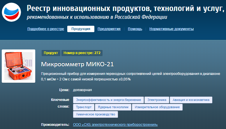
MIKO-21 is designed for high precision measurements of DC electrical resistance in the range from 0.1 µΩ to 2 Ω with an accuracy of ±0.05% and can test:
contacts of high-voltage circuit breakers of all types and voltage classes;
contactors, relays, busbars, various bolted connections, welded joints, brazed joints;
elements of equipment for open and closed switchgears in extreme electric and magnetic field conditions;
in research laboratories and industrial workshops.
MIKO-21 is ahead of similar devices represented on the market due to a number of functional and technical features. For example, special measuring technologies ensure MIKO-21 compliance with the most stringent accuracy requirements. MIKO-21 is ideally applicable for high precision resistance tests in the µΩ range.
Watch detailed video-reviews about MIKO-21 micro-ohmmeter up above ↑ or on the video page
One of the problems during contact resistance measurement with permissible error is availability of oxide films between contact surfaces.
According to international standard IEC 62271-1: Common Specifications for Alternating Current Switchgear and Controlgear (International Electrotechnical Commission), to control this type of error test current amperage during testing the electric resistance in the main circuit of a HV circuit breaker shall be between 50 A and its rated value.
Test current in circuit breakers is often limited by specific values: 100 A and 200 A.
The amperage in MIKO-21 can be set in several ways:
By selecting from a number of specified values: 10 A, 50 A, 100 A, and 200 A;
By setting the automatic mode for selecting test current;
By setting test current manually in the range from 1 A to 200 A at a step of 1 A.
SKB EP micro-ohmmeters are the only instruments enabling to measure contact resistance of live tank and dead tank circuit breakers using separate automatic modes optimized for those circuit breakers.
Mode 1 makes it possible to carry out measurements in the circuits without CT;
Mode 2 enables to operate measurements in the circuits with CT with minimal battery power consumption;
Mode 3 enables to operate measurement in the circuits with CT using 100 A or 200 A test current (set by a user) without saving battery power.
Current transformers of dead tank circuit breakers form an extended transition process when test current is applied. Due to that measurement time is determined by the parameters of CTs, their number, and test current. For example, for HV oil-blast circuit breakers measurement time may be up to 30 seconds.
MIKO-21 special algorithms with automatic measurement stop prevent subjective errors and increase number of measurements per one battery charge.
Four ways are programmed in the instrument to start resistance measurement:
Single is started once the cable clamps are contacted to the tested object and followed by pressing the START button.
Auto single circuit is initiated by pressing the START button. The instrument will start measurement when the electric contact between the tested circuit and the test cable contacts is set. The test can be repeated by pressing the START button again.
Periodic is used in pre-specified time intervals when both hands are occupied with cable probes pressing against the test points. The user can choose time interval between the tests. The instrument will work continuously until the user stops the mode.
Auto periodic circuit is initiated by pressing the START button and used for continuous measurements. The user connects the current cable, and as soon as the potential contacts are connected, the measurement will start automatically. To repeat a test, simply break contact with potential probes and reconnect.
The instrument contains a built-in database that contains nominal values of high-voltage circuit breakers indicating the maximum and/or minimum permissible values of contact resistance. There are also the nominal values for rejected resistors indicating the acceptable values of the upper and lower thresholds of resistance.
The user can add / edit / delete the nominal values of the exact measured object.
Availability of a built-in archive of nominal values of electric resistances (main circuit resistance of HV circuit breakers) facilitates automatic detection, and once the measured value exceeds the nominal value it is highlighted with red colour.
This mechanism works due to either the built-in database of nominal values or the ability to add / edit / delete the nominal data of the measured object independently.
Color graphic display of high brightness ensures easy reading on a sunny day, whereas intuitively understandable interface with a multi-sensor display simplifies the instrument use.
The Instrument can be manipulated either from the keyboard or from the multi-sensor display, as suits.
Communication with PC via USB or a flash card facilitates data transfer from the Instrument to the company data base. The device can be integrated into measuring systems under PC control of diagnostic laboratories and companies producing electric equipment.
Battery power, low weight and small dimensions ensure complete independence and high mobility of the device in the vast territory of the substation or workshop, and the built-in memory for 2,000 measurements greatly simplifies the process of diagnostics and data transfer from the substation into the company office.
For convenient connection to the object, there are special test cables of different lengths and different types of clamps:
Test cables with Kelvin clamps 2 m long (standard complete set) for high voltage circuit breakers up to 10 kV;
Test cables with Kelvin double hand spikes 1.5 m long for measurement in pipelines and interrupting chambers (recommended when the device is placed near the circuit breaker);
Test cables with Kelvin C-clamps 4.5 m and 6 m long (recommended when the device is placed near the circuit breaker) for circuit breakers from 10 kV to 220 kV;
Test cables that consist of a cable with Kelvin clamp and Kelvin C-clamp 3 m, 6 m or 9 m long (recommended when the device is places in a cradle of a lift) for circuit breakers from 220 kV to 750 kV;
Test cable for precise measurements and measurements on sections of the electric circuit, to the end points of which the test current is applied.
Number of digits in the output of the measurement result
5
Accuracy
±0.05 %
Time of measurement in Mode 1, sec
not more than 2
Time of measurement in Mode 2 on a dead tank circuit breaker with a built-in CT (energy saving), sec
10 - 30
Time of measurement in Mode 3 on a dead tank circuit breaker with a built-in CT (without energy saving), sec
5 - 15
Mains voltage
90-264 V AC, 47-63 Hz 127-370 V DC
Consumed power does not exceed, W
60
Battery type
Li-Ion
Battery lifetime (in continuous operation), hrs
more than 8
Battery recharge time, hrs
less than 2
Built-in memory
2,000 measurements
Number of tests (max. current, I=200A)
more than 500
PC communication
USB / USB Flash
Display
Color graphic display, touch-screen, 480 x 272 pix
Interface, User manual language
English
Environmental protection with closed cover
IP 67
Environmental protection with open cover
IP 40
Storage temperature, ºС
-20 - +60
Operating temperature, ºС
-20 - +50
Relative humidity, % (non condensing)
95
Dimensions, mm
270 х 246 х 124
Test block weight, kg (lbs)
3.3 (7.28)
Testing period, years
3
Calibration period, years
3
Warranty period, years
3
Standard complete set
Photo
Item, Index
Application
Main instrument MIKO-21
039.00.00.000
Main instrument MIKO-21
039.00.00.000
<p>
Instrument and additional documents: Calibration Certificate, User Manual, Log Book.
</p>
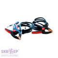
Test cables<br>Set #2
039.27.00.000
Test cables<br>Set #2
039.27.00.000
<p>
200 A Kelvin clamp test cable 2 x 2 m (1.12 kg) with jaw up to<br>50 mm, for circuit breakers of up to 10kV.
</p>
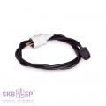
Mains cable
018.09.00.000
Mains cable
018.09.00.000
<p>
Mains cable 1 x 2 m (0.24 kg). For instrument connection to the mains. Operating temperature range -25°С - +120°С. Rubber insulation.
</p>
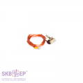
Ground cable
010.01.00.000
Ground cable
010.01.00.000
<p>
Ground cable 1 x 2 m (0.07 kg) for instrument grounding. The cable is equipped with a C-clamp and a screw end cap. Rated current is 50 А.
</p>
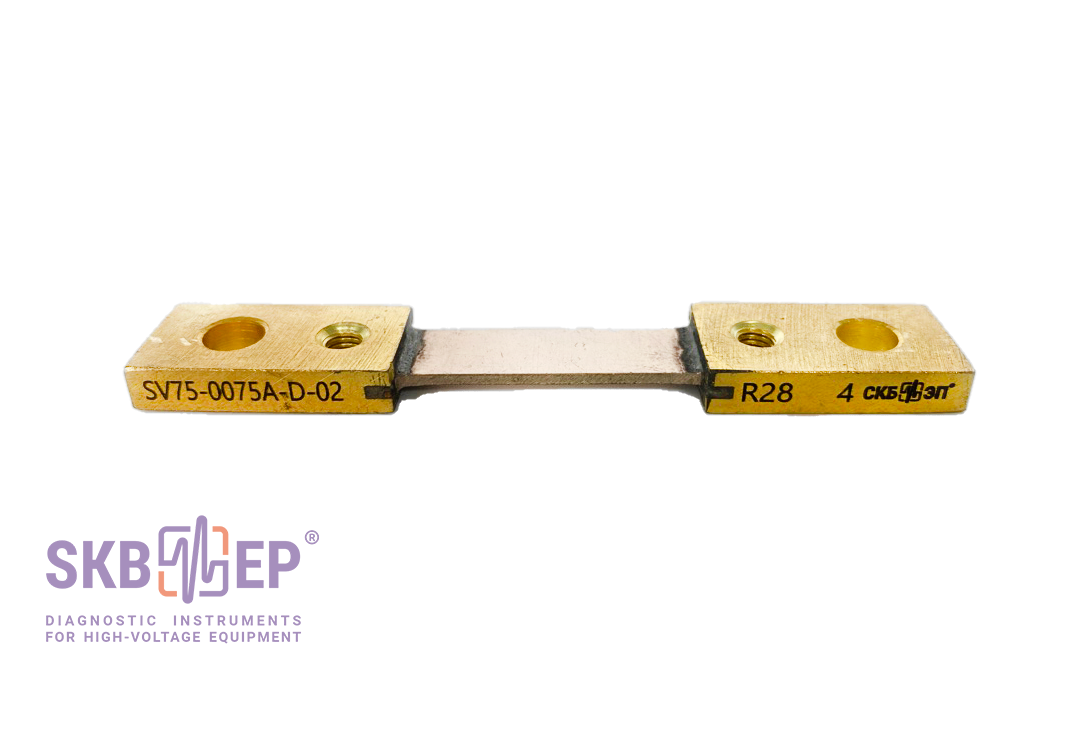
Shunt
Shunt
<p>
Type: SV75-0075A-D-02. For checking MIKO-21 operability. SKB EP part.
</p>
Fuses
Fuses
<p>
Type: VP2B-1V-2A (ВП2Б-1В-2А) (2 pcs). For the power source protection.
</p>
Tool bag
126.06.00.000
Tool bag
126.06.00.000
Convenient, robust, wear proof bag for transportation of cables, documentation and other accessories to MIKO-21.<br>
Weight 0.6 kg.
Test cables, if the instrument is placed near the circuit breaker (on order)
Photo
Item, Index
Application
Test cables<br>Set #1
039.19.00.000<br>039.19.00.000-01
Test cables<br>Set #1
039.19.00.000<br>039.19.00.000-01
<p>
200 A Kelvin double hand spike test cable 2 x 1.5 m (0.9 kg) for measurements in busbars or in arc extinguish chambers.
</p>
Test cables<br>Set #4
039.26.00.000
Test cables<br>Set #4
039.26.00.000
<p>
200 A Kelvin С-clamp test cable 2 x 6 m (5.6 kg) with jaw up to<br>80 mm, for all the circuit breakers of up to 110 kV and some circuit breakers of up to 220 kV.
</p>
Test cables<br>Set #3
039.25.00.000
Test cables<br>Set #3
039.25.00.000
<p>
200 A Kelvin С-clamp test cable 2 x 4.5 m (3.8 kg) with jaw up to<br>80 mm, for all the circuit breakers of up to 35 kV, and for some circuit breakers of up to 110 kV.
</p>
<p>
Optional potential test cable with crocodile clips A25C (2 pcs) and probes (2 pcs) for precise measurements and for measurements on the sections of the electric circuit, to the end points of which the test current is applied.
</p>
<ul>
<li>To be used together with Set #2 - Length 2 m (39.24.00.000)</li>
<li>To be used together with Set #3 - Length 4.5 m (39.24.00.000-01)</li>
<li>To be used together with Set #4 - Length 6 m (39.24.00.000-02)</li>
</ul>
<p>
In particular, the cable can be used in case of measurement of cables resistivity.
</p>
Test cables<br>Set #2
039.36.00.000
Test cables<br>Set #2
039.36.00.000
<p>
200 A Kelvin clamp test cable 2 x 5 m (2.20 kg) with jaw up to<br>50 mm, for all the circuit breakers of up to 10 kV and some circuit breakers of up to 220 kV.
</p>
Test cables<br>Set #2
039.35.00.000
Test cables<br>Set #2
039.35.00.000
<p> 200 A Kelvin clamp test cable 2 x 10 m with jaw up to<br>50 mm, for all the circuit breakers of up to 35 kV.</p>
Test cables<br>Set #4
039.38.00.000
Test cables<br>Set #4
039.38.00.000
<p>
200 A Kelvin С-clamp test cable 2 x 10 m with jaw up to<br>80 mm, for all the circuit breakers of up to 110 kV and some circuit breakers of up to 220 kV.
</p>
Test cables
039.43.00.000
Test cables
039.43.00.000
Kelvin clamp test cables 2 x 10 m (15.8 kg total) with jaw up to 70 mm, for all the circuit breakers of up to 35 kV.
Test cables, if the instrument is placed in the lift cradle (on order)
Photo
Item, Index
Application
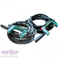
Test cables<br>Set #5
039.20.00.000<br>039.21.00.000
Test cables<br>Set #5
039.20.00.000<br>039.21.00.000
<p>
Test cable kit for circuit breakers of up to 220 kV.
</p>
<ul>
<li>200 A Kelvin clamp test cable 1 x 1 m (0.5 kg) with jaw up to 50 mm.</li>
<li>200 A Kelvin C-clamp test cable 1 x 3 m (1.3 kg) with jaw up to 80 mm.</li>
</ul>
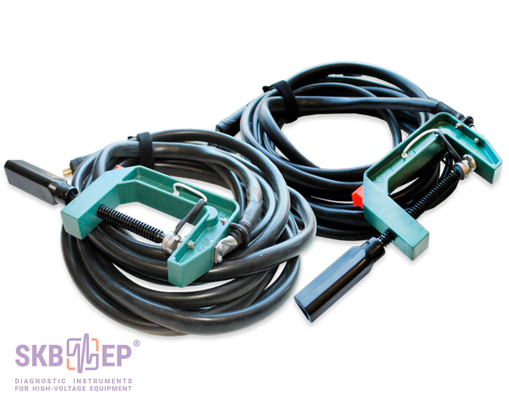
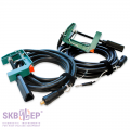
Test cables<br>Set #6
039.20.00.000<br>039.21.00.000-01
Test cables<br>Set #6
039.20.00.000<br>039.21.00.000-01
<p>
Test cable kit for circuit breakers of up to 330 kV, and some of up to 500 kV.
</p>
<ul>
<li>200 A Kelvin clamp test cable 1 x 1 m (0.5 kg) with jaw up to 50 mm.</li>
<li>200 A Kelvin C-clamp test cable 1 x 6 m (2 kg) with jaw up to 80 mm.</li>
</ul>
Test cables<br>Set #7
039.20.00.000<br>039.21.00.000-02
Test cables<br>Set #7
039.20.00.000<br>039.21.00.000-02
<p>
Test cable kit for circuit breakers of up to 750 kV.
</p>
<ul>
<li>200 A Kelvin clamp test cable 1 x 1 m (0.5 kg) with jaw up to 50 mm.</li>
<li>200 A Kelvin C-clamp test cable 1 x 9 m (4 kg) with jaw up to 80 mm.</li>
</ul>
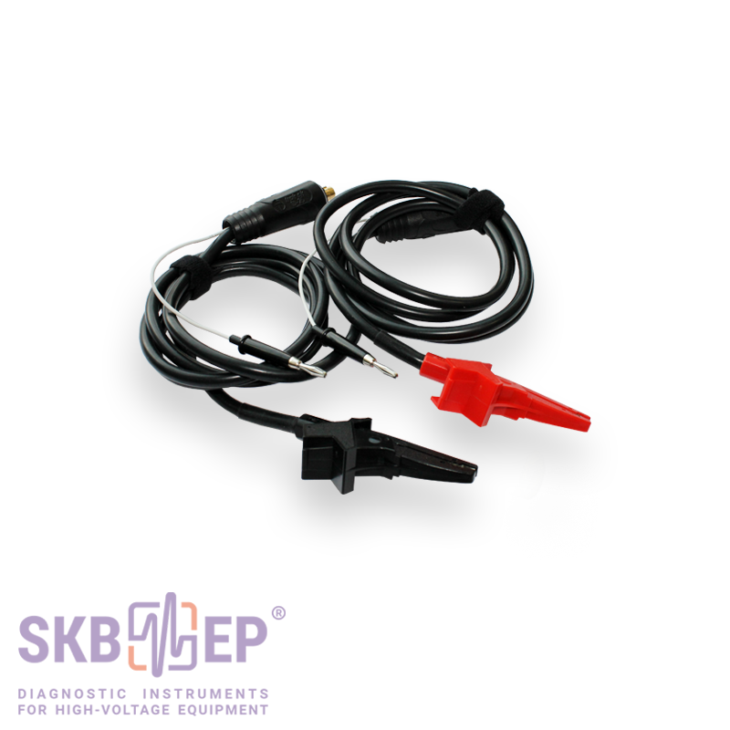
Additional accessories (on order): measurement cables for aviation
Photo
Item, Index
Application
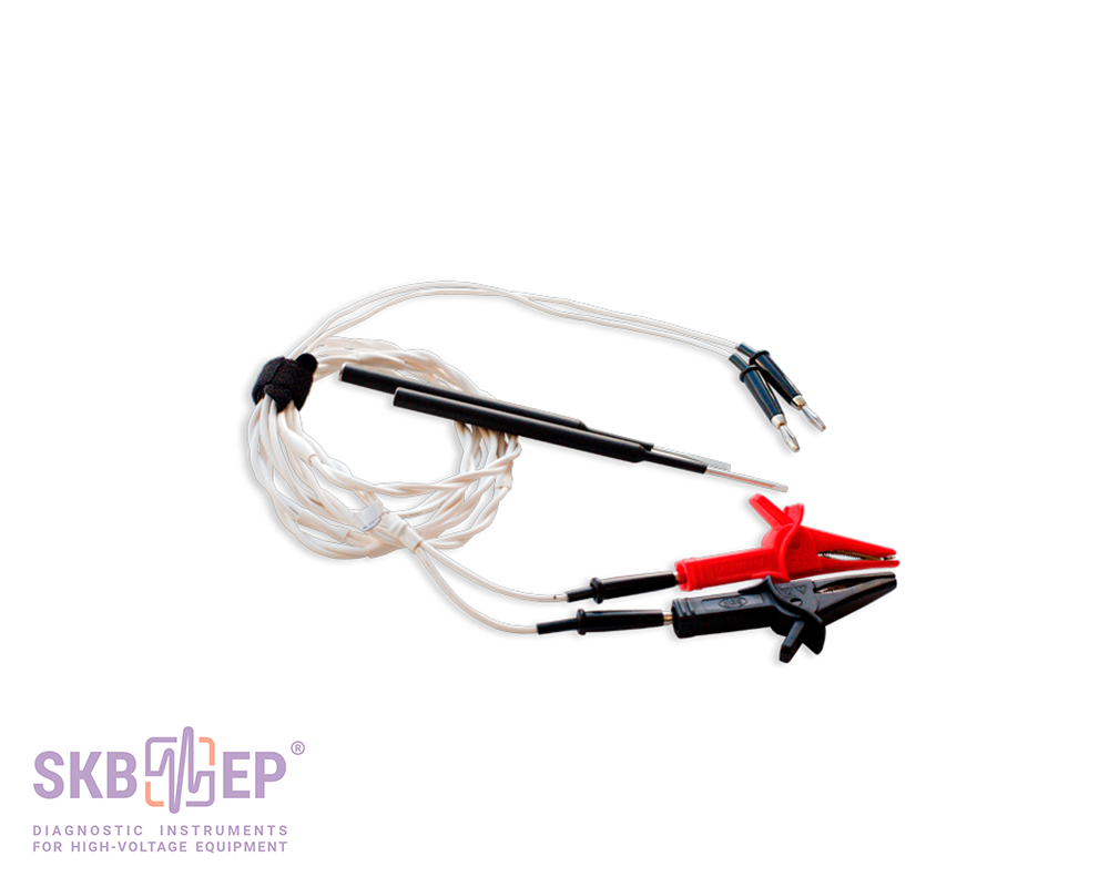
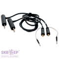
Test cable set
039.31.00.000
Test cable set
039.31.00.000
50 A Kelvin test cable with crocodile clips 2 x 1.5 m with jaw up to 20 mm. Recommended for resistance measurements in hard-to-reach places; in aviation: for resistance measurement of various elements of the aircraft.
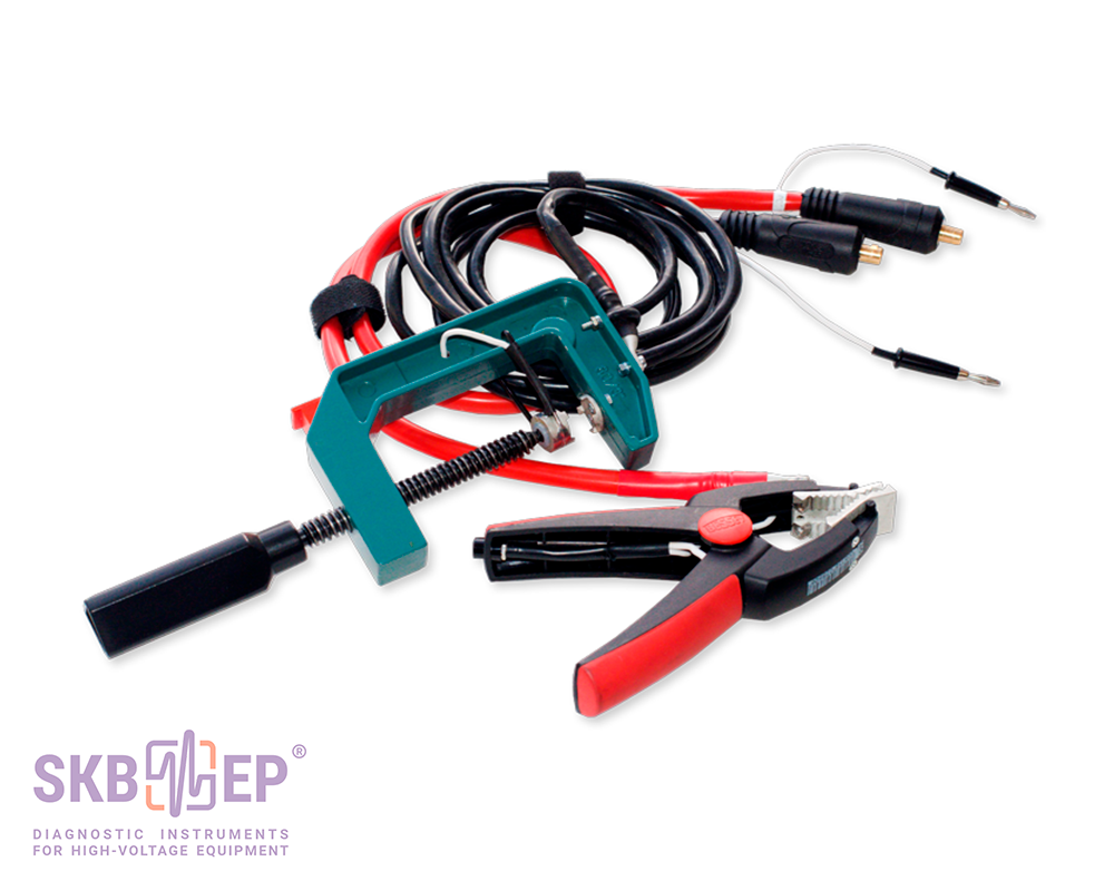
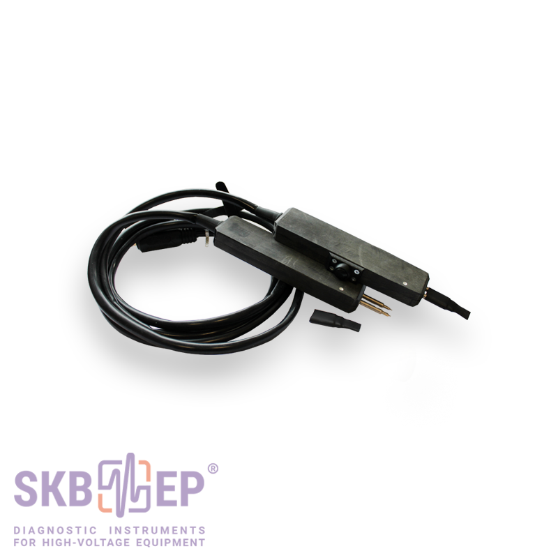
Test cable set
039.33.00.000 039.33.00.000-01
Test cable set
039.33.00.000 039.33.00.000-01
100 A Kelvin double hand spike test cable with spring-loaded contacts with Ø 5mm, 2 x 1.5 m. One probe is equipped with a control button for measurement start-up. <br>
Recommended for contact resistance measurement in hard-to-reach places of objects with painted surfaces; in aviation: for contact resistance measurement of aircraft equipment and helicopter fuselage.
Additional accessories (on order)
Photo
Item, Index
Application
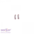
Potential spring-loaded contact (2 pcs.)
023.21.00.000
Potential spring-loaded contact (2 pcs.)
023.21.00.000
<p>
To be used together with sets #2-7 for avoiding high contact resistances between an input pin and a clamp of the device.
</p>
Potential probe (2 pcs.)
023.22.00.000
Potential probe (2 pcs.)
023.22.00.000
<p>
To be used together with sets #2-7 for avoiding high contact resistances between an input pin and a clamp of the device.
</p>
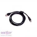
USB 2.0 A-B Cable
USB 2.0 A-B Cable
<p>
USB cable 1 x 1.8 m. For computer connection and data transfer.
</p>
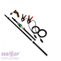
<p>
Manipulating rod is designed for test cables connection from the ground or from the tank cover to the bushings of high-voltage circuit breakers, and to the structural elements of high-voltage disconnecting switches and earthing devices, without the use of ladders or elevated platforms.
</p>
<p>
The manipulating rod is completed with special extension cables. There is a Kelvin clamp with current and potential contacts to connect to the object on one side, and a contact pad on the other side. The device test cable is connected to the contact pad from the ground or a tank cover.
</p>
<p>
Manipulating rod extension cable is made according to a four-wire (Kelvin) scheme with the test current capacity of 100 A in the presence of a good contact.
</p>
<ul>
<li><a href="/instrument/manipulating/" target="_blank">Manipulating rod</a> - 2.2 (length 2.2 m / weight as an assembled set 3.4 kg);</li>
<li><a href="/instrument/manipulating/" target="_blank">Manipulating rod</a> - 3.7 (length 3.7 m / weight as an assembled set 4.0 kg);</li>
<li><a href="/instrument/manipulating/" target="_blank">Manipulating rod</a> - 5.1 (length 5.1 m / weight as an assembled set 4.6 kg).</li>
</ul>
Official reviews from customers based on the results of operating SKB EP instruments are available upon request. Please, fill out the form on the website.
 Русский
 Français
 Chinese